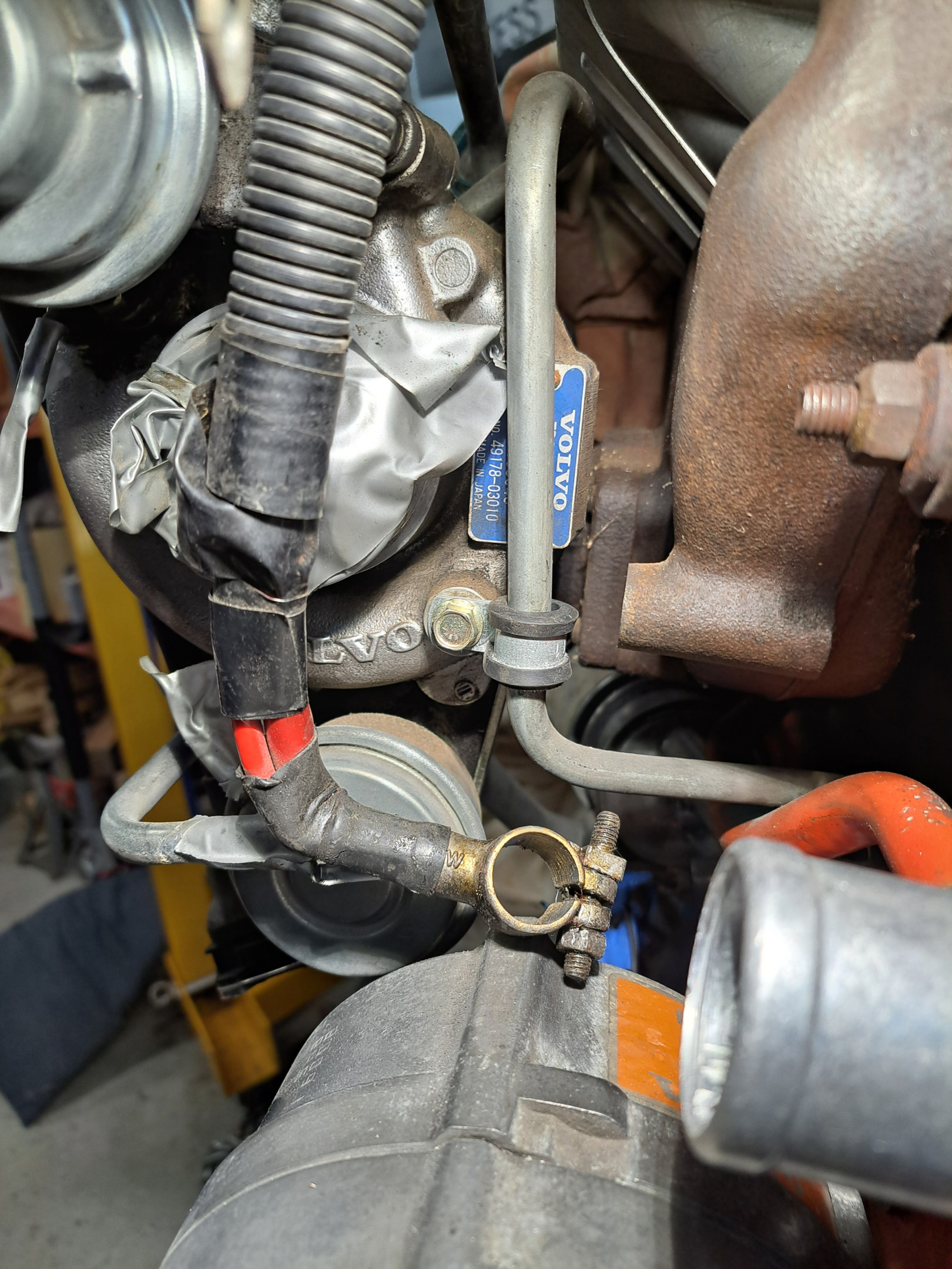
I've always ended up blocking that hole off, I use it for one of the wastegate bracket mounting points. As far as I can tell it has no specific purpose, I figure it's probably there so OEMs have some choice where they locate the wastegate pressure line.
Greg's Gold 1991 240GLE wagon B230FT-to-be

Got a few more things done…mounted the alternator with new bushes, and of course with the oil pressure sender in place the original belt size was too short (alternator touching sender). We had slightly longer (920 mm) belts which just eke by, but I may have to get some longer ones…reason being is if we try to use the original oil cooler lines bracket, that is sandwiched between the alternator bracket and block and will position the bottom of the alternator out the thickness of the bracket (about 2.5 mm) which will tighten up the belts even more. It was a bunch of f**kery to get the alternator bushes and alternator in place and I managed to smash my middle finger nail with the hammer so f**k you alternator and hammer (one of those days…that I remind myself I don't really enjoy working on cars LOL!)

6 days later
- Edited
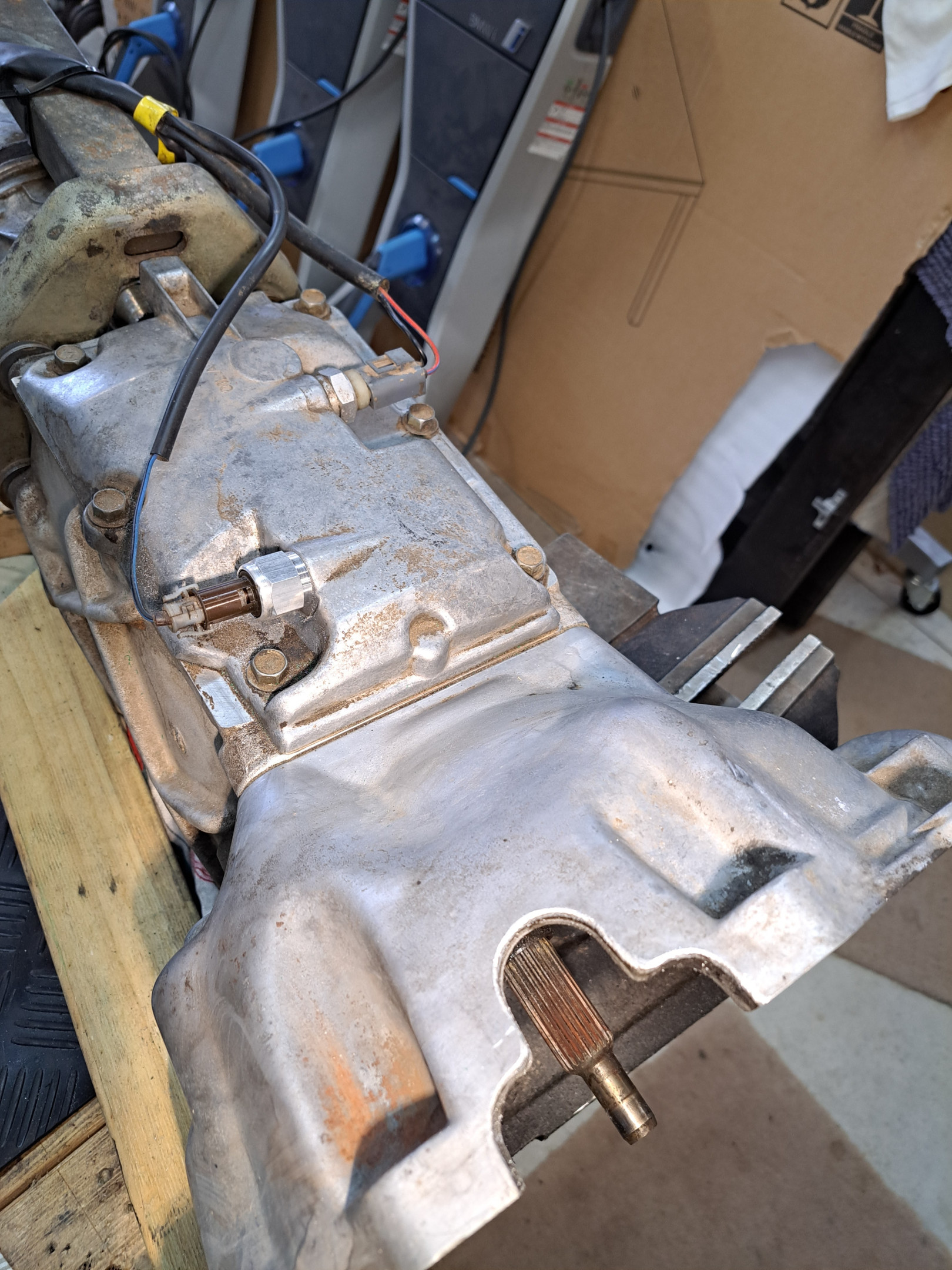
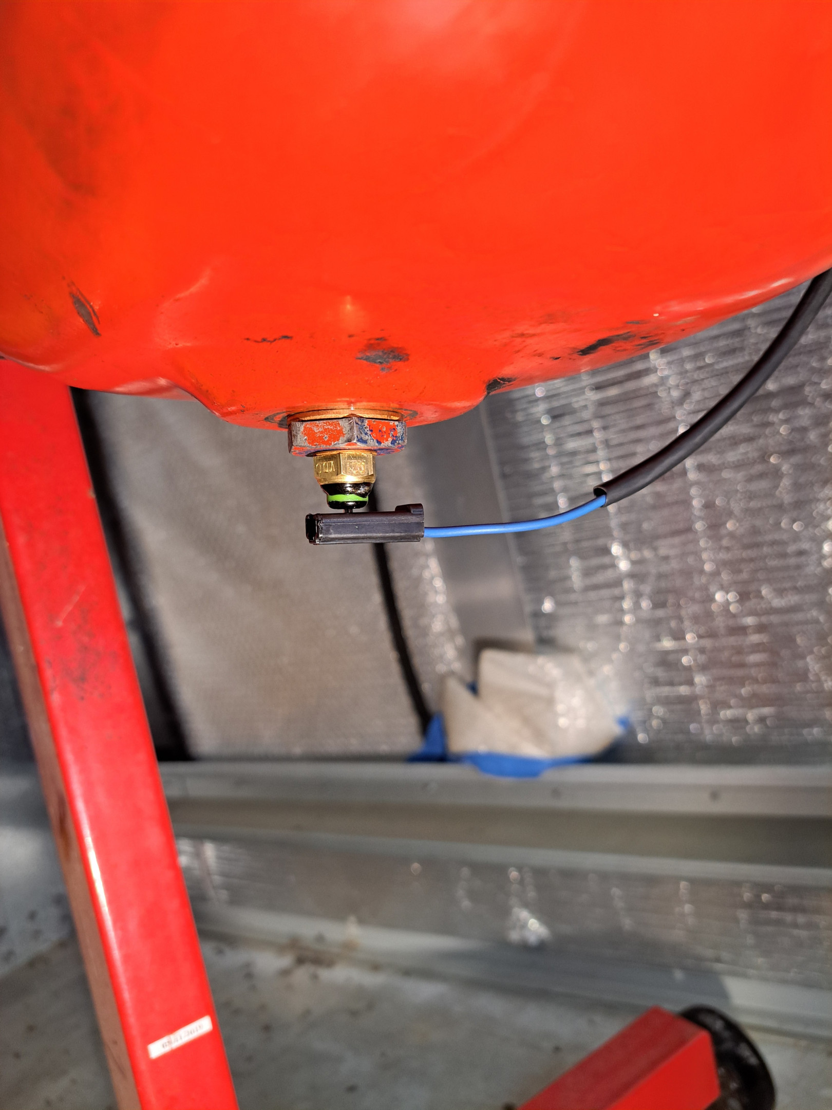
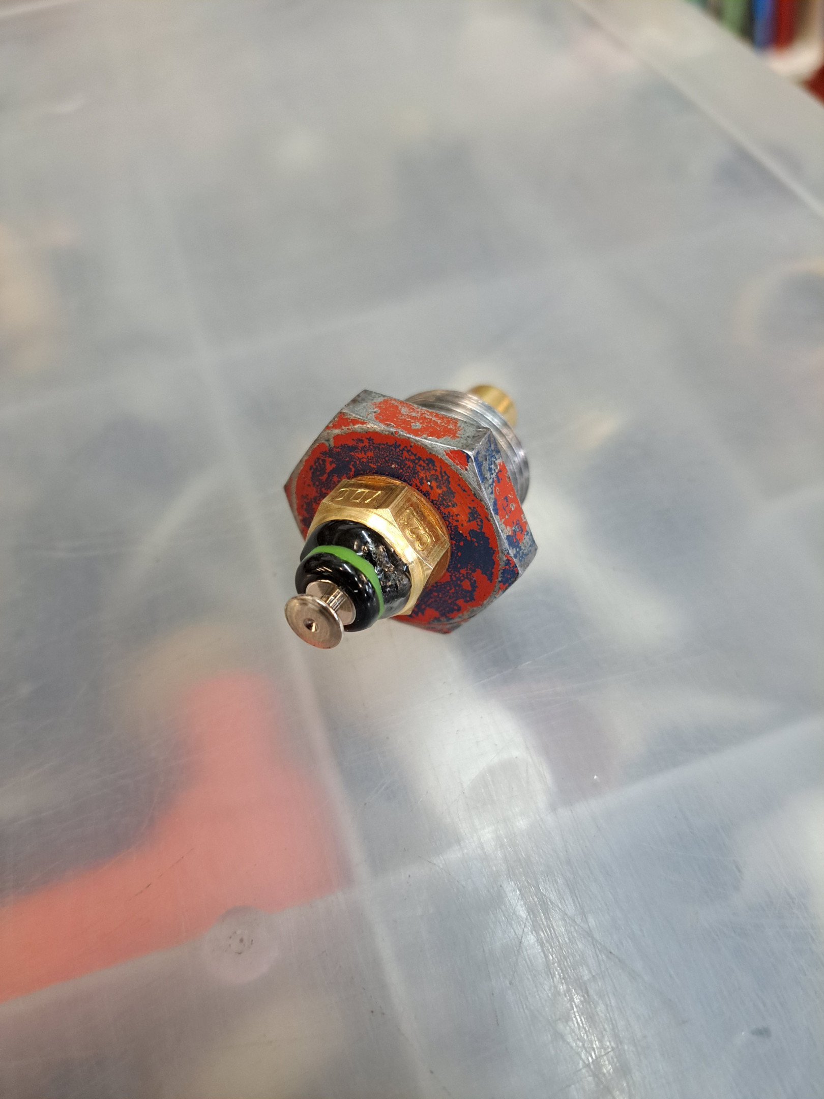
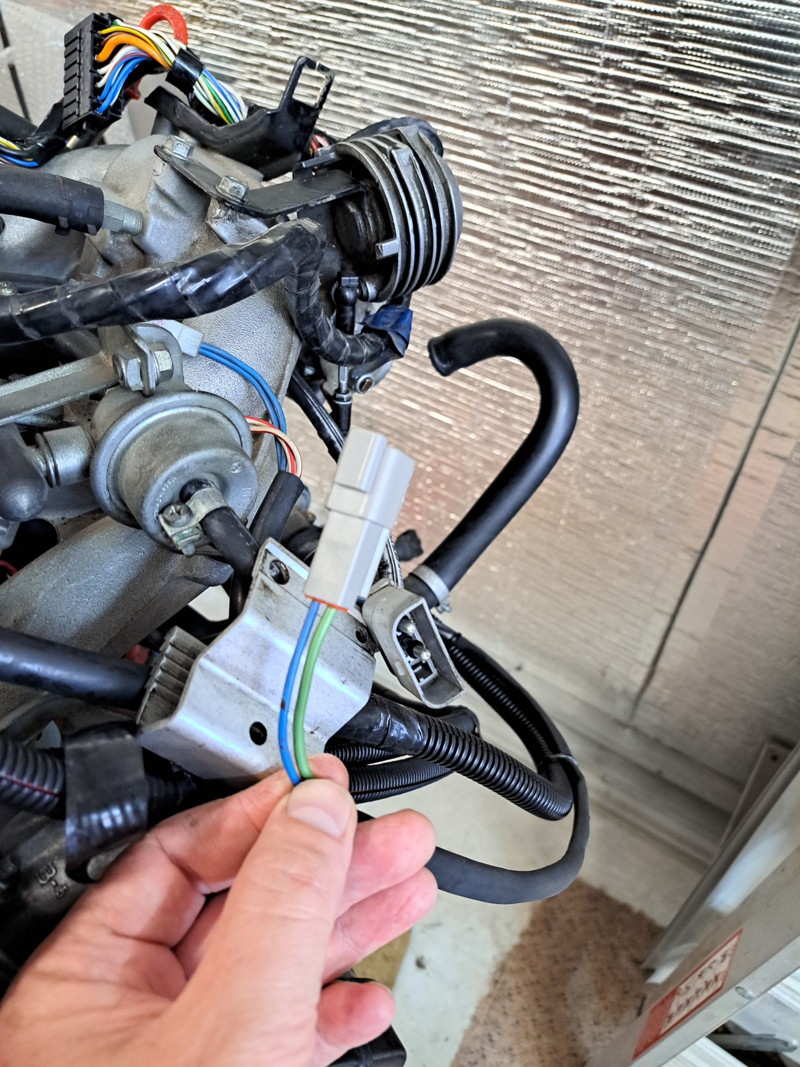
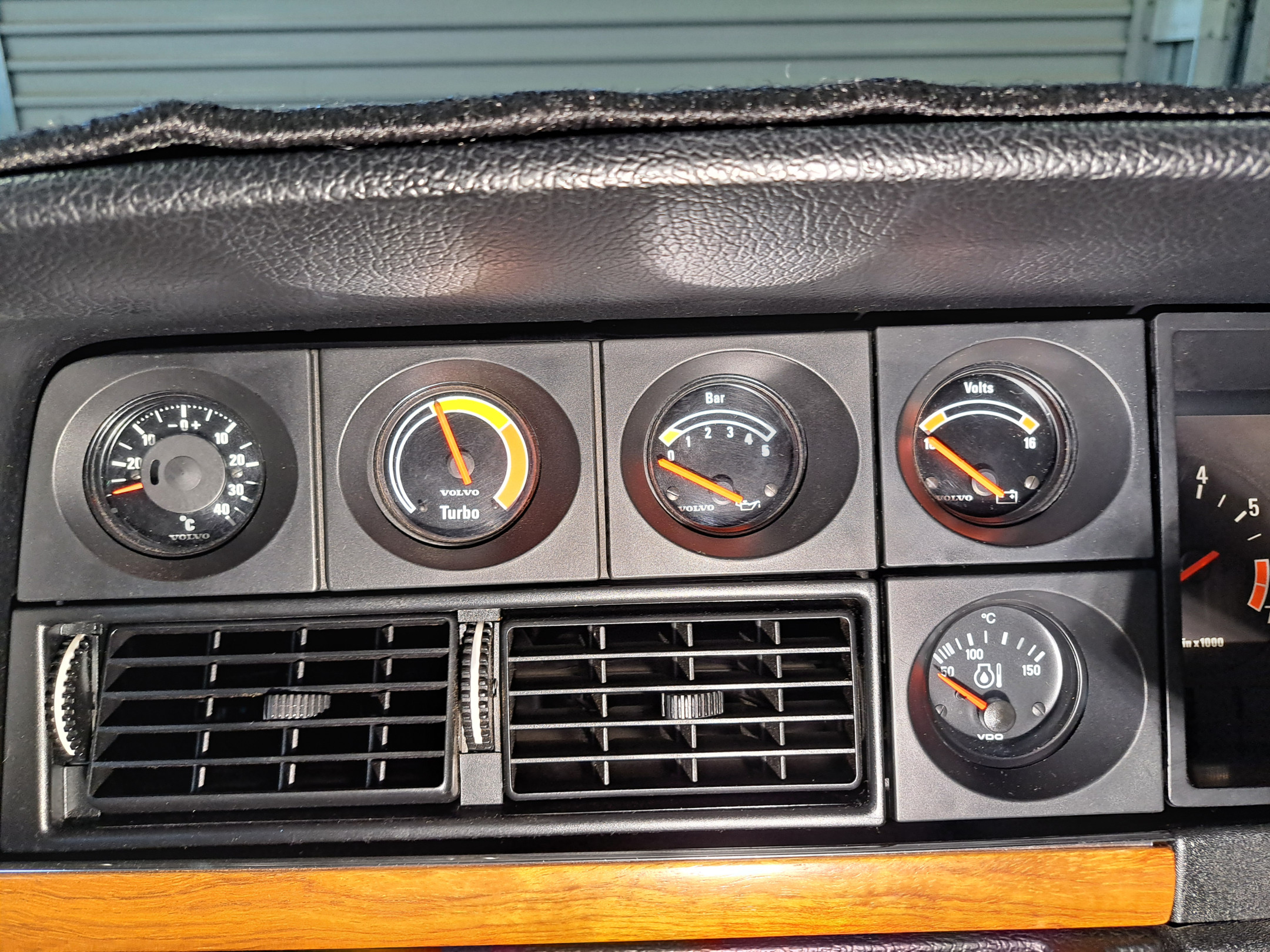
Have been making more slow progress. Got more wiring done (including wiring for VDO oil temp gauge). Drilled drain plug for oil temp sender and Wayne rigged up a fancy waterproof connector for the oil temp and oil pressure sender wires to join from engine harness to body. Got the 4th gear switch replaced and knocked out and cleaned up the bell housing cut-out for the crank sensor. Somebody really f**ked the transmission drain plug, so we were unable to remove it (I had a new one to go in). Ended up just topping up the fluid level. Realised I didn't have a good clutch fork to go in and the existing one is worn, so I ordered one from GCP. Next step is to try and swap out the rear output shaft flange on the gearbox from the 3-prong rubber donut style to the 4 bolt round flange. Hope that doesn't turn into another cluster f**k. Fun and games! Dad has been helping clean up a lot of the parts before we put things back together. Really hoping to get the engine back in soon, then we'll just be waiting for the clutch fork really before the gearbox can go in. Haven't tried fitting the downpipe yet. It's a 2.5 inch SS job from Classic Swede. Looks like the flared part of the flange is slightly too large to fit between the 3 studs on the turbo's mating flange ring, so that may require some finesse. Opted to ditch the oil cooler as it was all too hard for the time being. Since I'll probably only drive the car twice a year, doesn't seem worth it LOL! Will watch oil temps and see how things go. May put a remote oil filter/oil cooler setup on one day.**

carnut222 Next step is to try and swap out the rear output shaft flange on the gearbox from the 3-prong rubber donut style to the 4 bolt round flange.
AFAIK, the 1140 and 1310 flanges both have the same number of splines on the output shaft, so hope it goes to plan for you.
4 days later

The drain plug nightmare- being a fussy type i would carefully file / carefully grind (very thin wheel) another hex on it. Start with two opposing flats and check parallel with a vernier. Then next flats, it doesn't have to perfect, then lightly hammer on an old suitable socket, followed by an rattle gun, done.
Hour or two should do it.
(Before rattle guns, i would heat up the surrounding alloy), others might weld on a nut.
Keen to hear when you get the drainplug out ( and thrown in the bin)
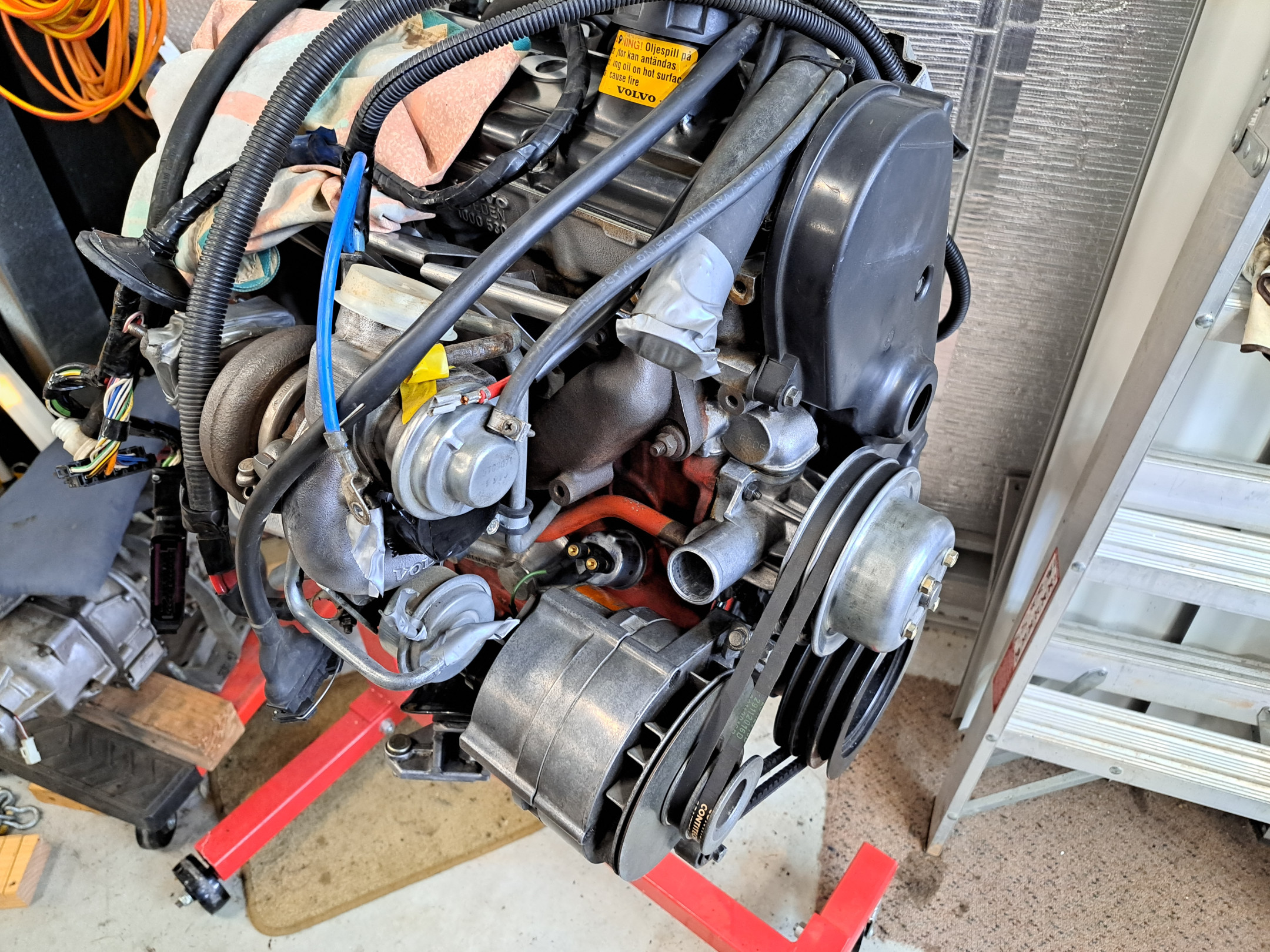
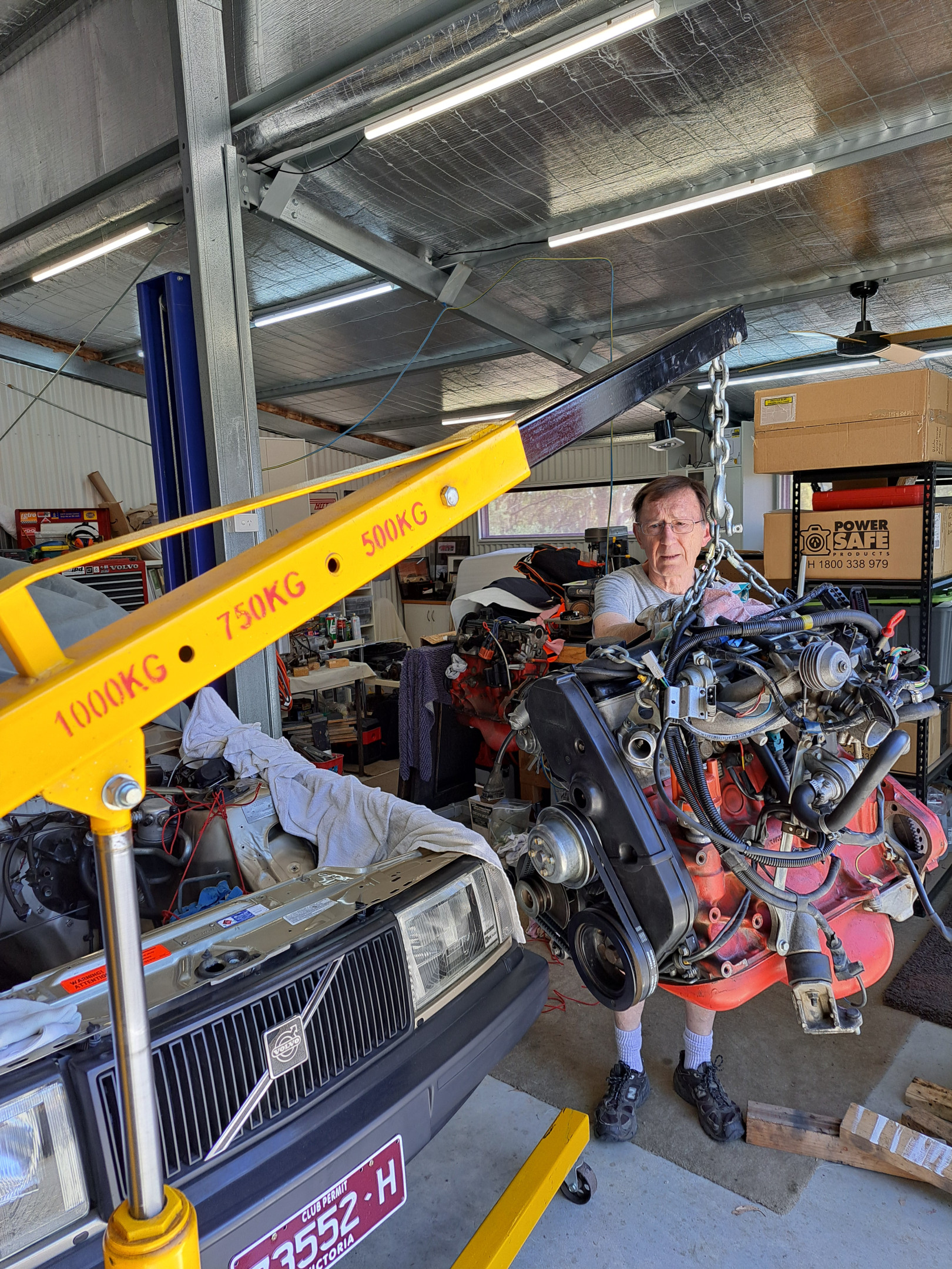
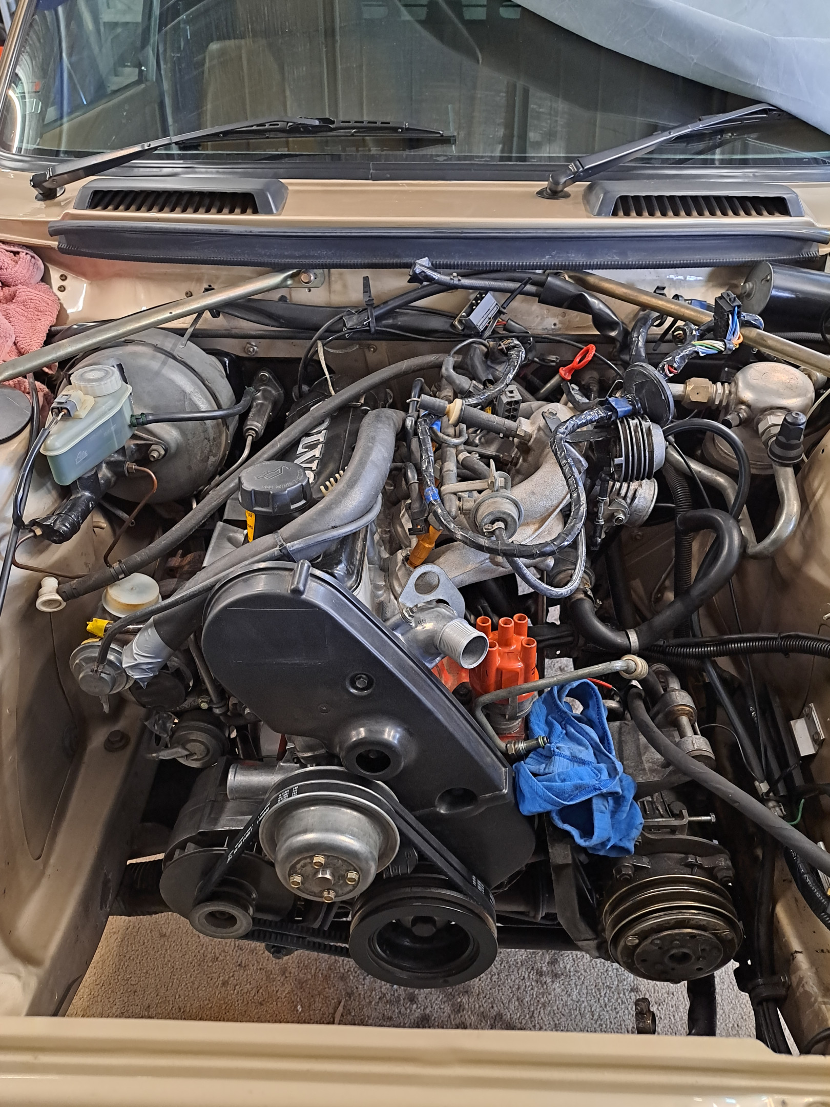
Well, we got the engine in today! Yay! Waiting for clutch fork from GCP, then we'll be ready to put the gearbox in. Progress! We'll start to fit some of the ancillaries etc. in the engine bay and hook up the wiring, fuel hoses etc. while we're waiting for the clutch fork.
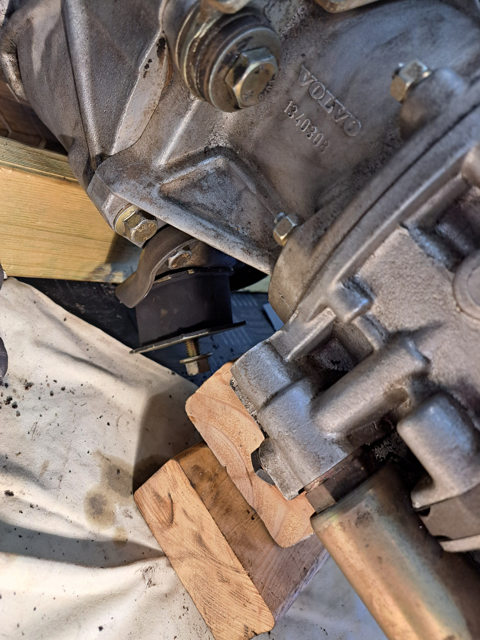
Everything looks pretty tight as expected on the turbo side, but hard to say exactly until the gearbox and rear mount are in (currently engine is just sitting with front mounts and a block of wood propping it against the firewall at the back of the cam cover).
Brake & Clutch masters- Interesting your sharing the same reservoir. (I keep independent reservoirs on 240T).
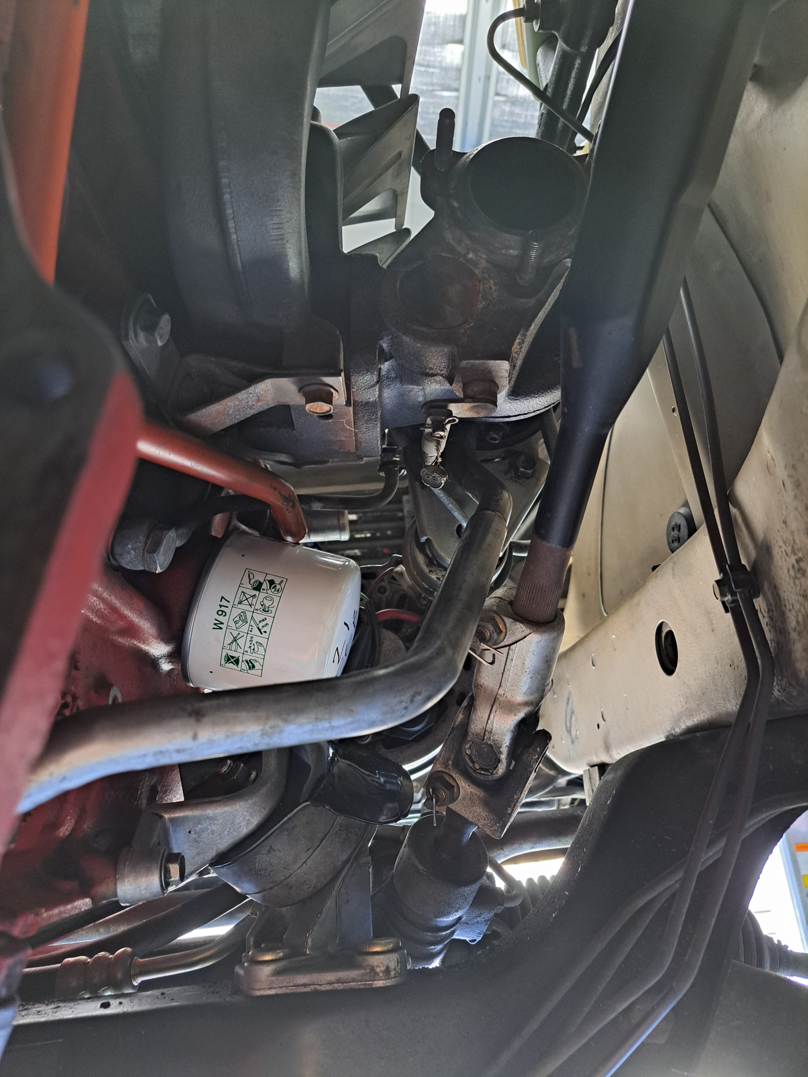
Clutch master cyl pipe routing - Notice it goes down to the hot turbo exhaust activity area (and then over the gearbox)
To solve this, I swung the line up and along the wiring loom.
Pic attached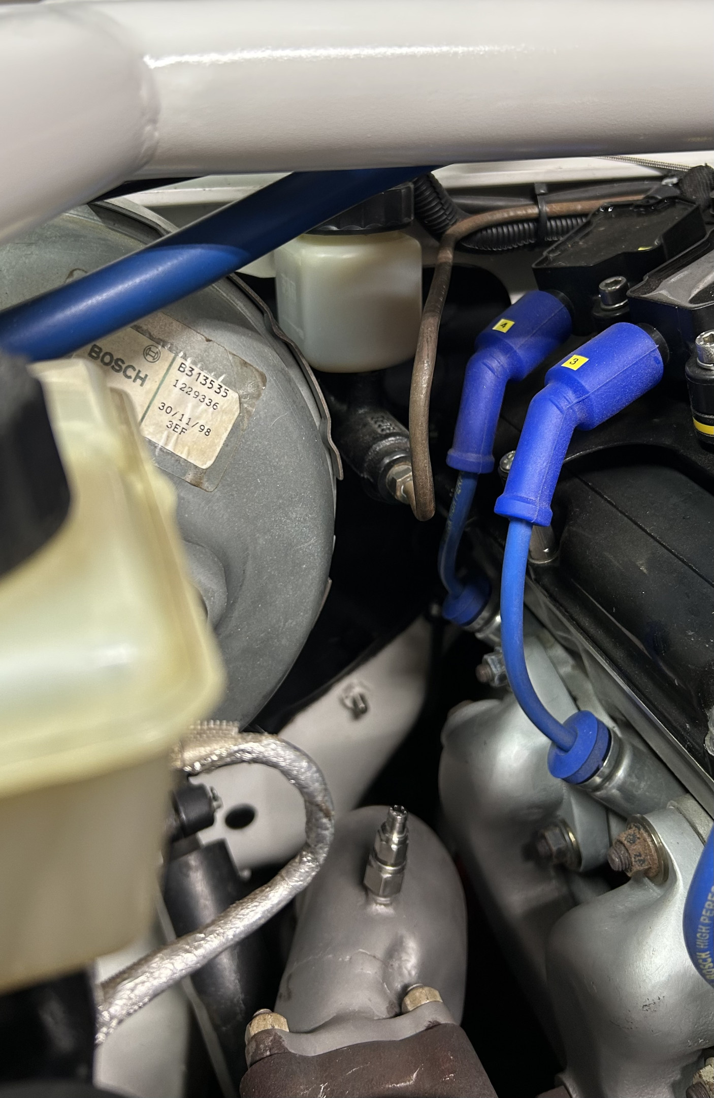
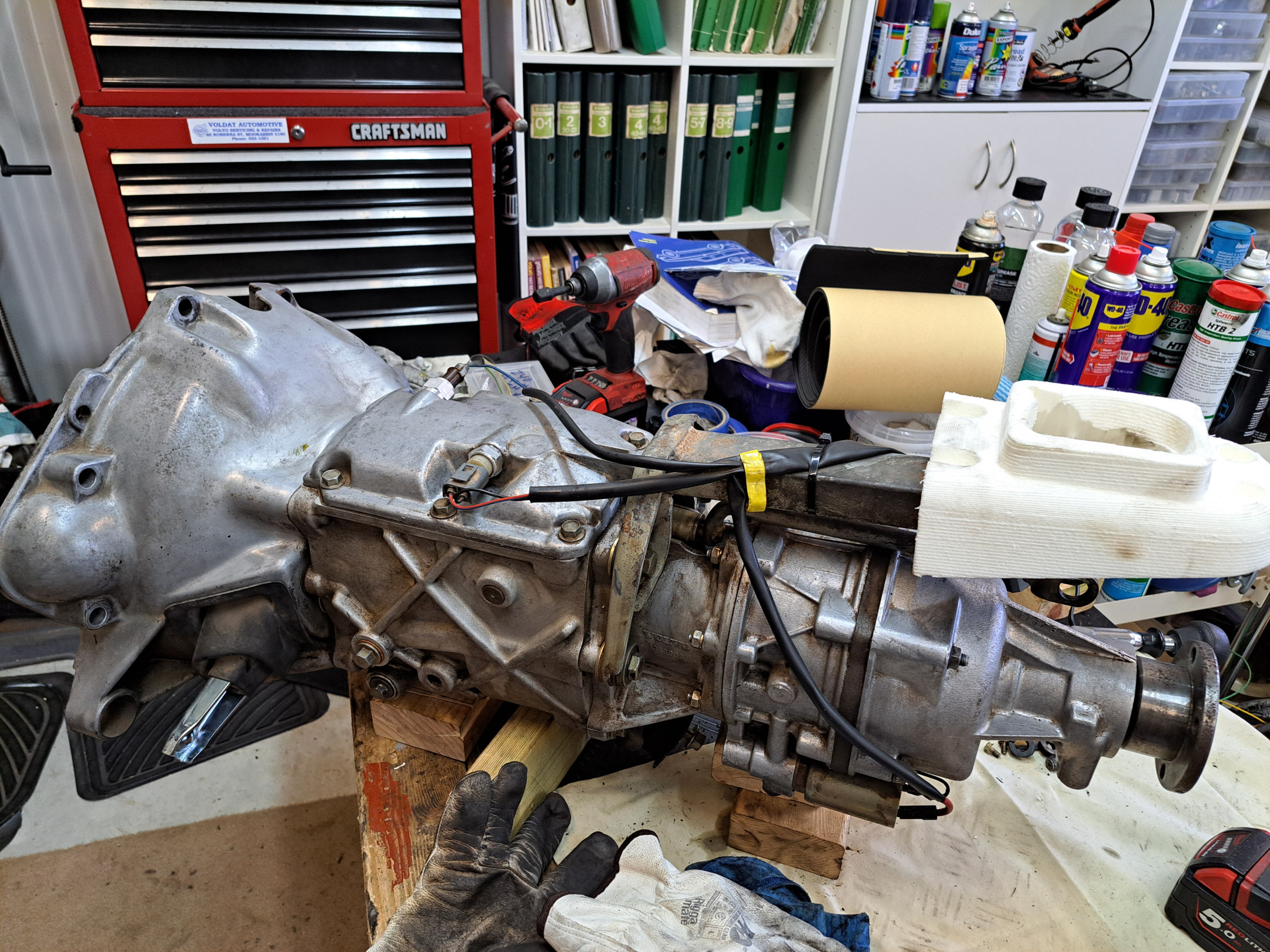
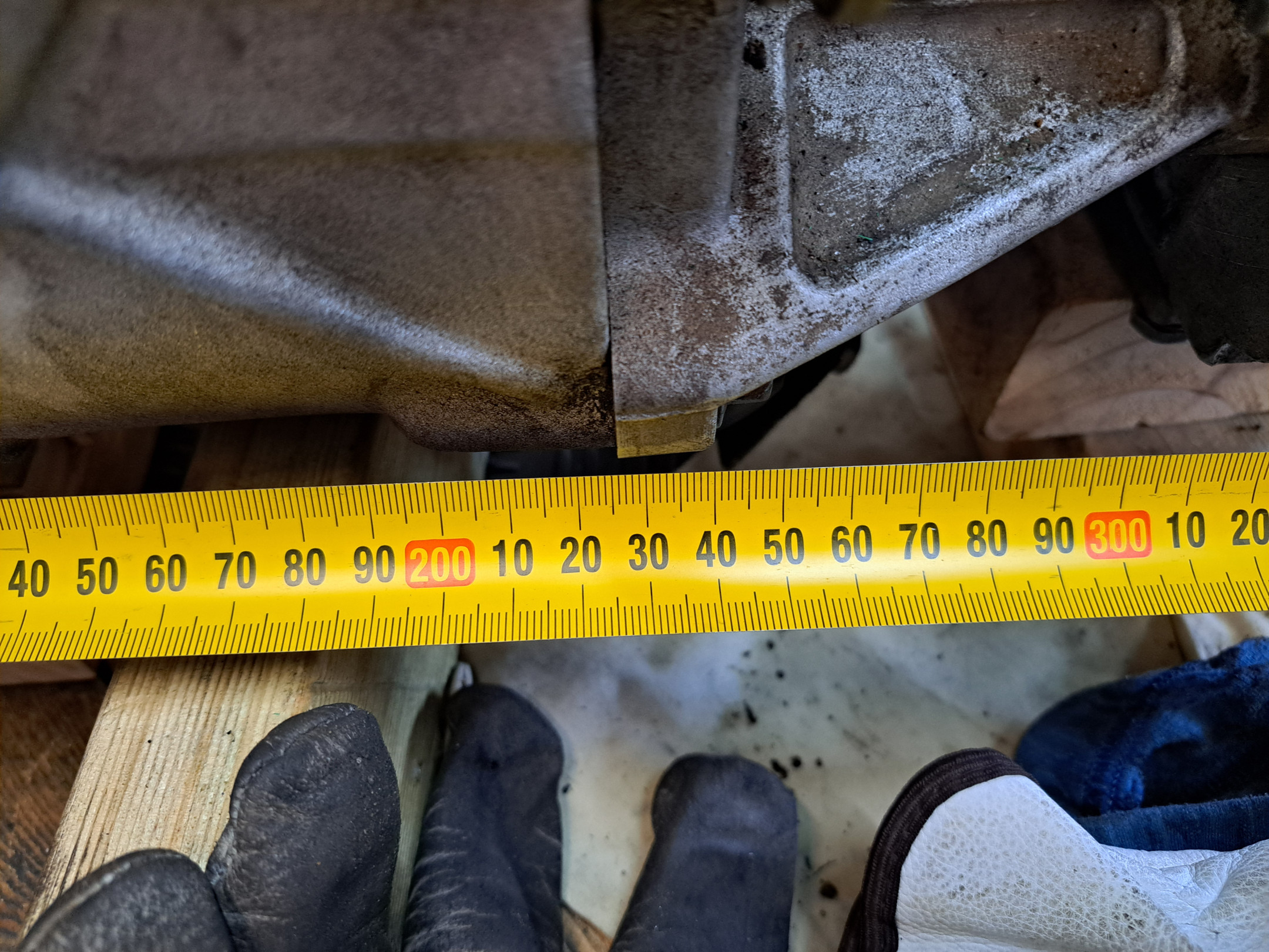
Got the clutch fork from GCP today so have that and throw-out bearing installed on gearbox. Got the clutch plate and clutch cover installed on flywheel, as well as crank sensor bracket and sensor on engine. Removed alloy 740 gearbox mount from back of gearbox and installed 240 mount in its place. I need to measure a cast iron case M46 length just to confirm the gearbox mount is in the same position as on the alloy case M46 as last thing I want is to get the box up into position and find out the mount bracket or cross member needs modification.  Trimmed up the foam gear lever surround as the only one available was one for a different gearbox. Doesn't fit great but better than nothing. I can put a bit more insulation around the gear lever once the gearbox is installed if need be. Hopefully tomorrow we'll get the gearbox installed.
Good progress.
If you need a measurement check i have a cast iron M46 / Overdrive box to hand.
PM if required.
We fought with the gearbox this morning trying to get it in (you'd think it would be easy with a hoist and a gearbox lifter). No luck. I had a block on the back of the engine/head area to hold the engine up at the back, but I guess that was too thick. So we put the car down. made a cross member with a threaded rod and hook to support at the rear lift eye. Lifted engine up, removed wood block, then let engine down quite a bit. Hopefully we'll have enough room to get the bell housing past the tunnel now. Lunch break now!

Sounds odd, clutch assembly lined up properly?
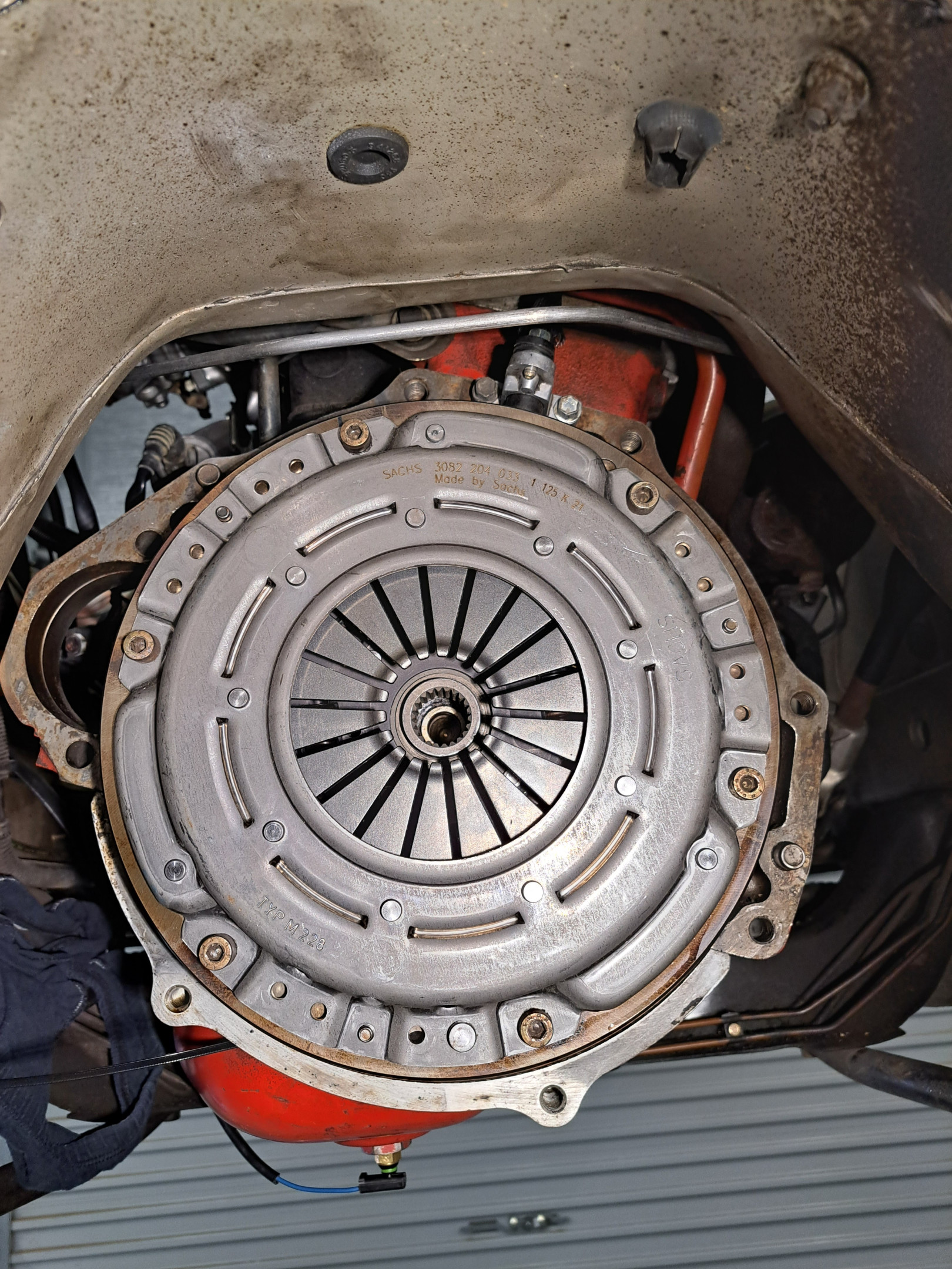
arebee We got it in eventually. Engine wasn't down low enough at the back. Once we lowered it as much as it would go (removed the wood block I had in there, and head against firewall basically, except for the extra thickness of the head of the 10 mm bolt holding the new cam plug blow-out plate). I think that 10 mm bolt head made a difference, but we were able to get it in without removing the bolt (which would have been a bitch).
Here's the proof! 
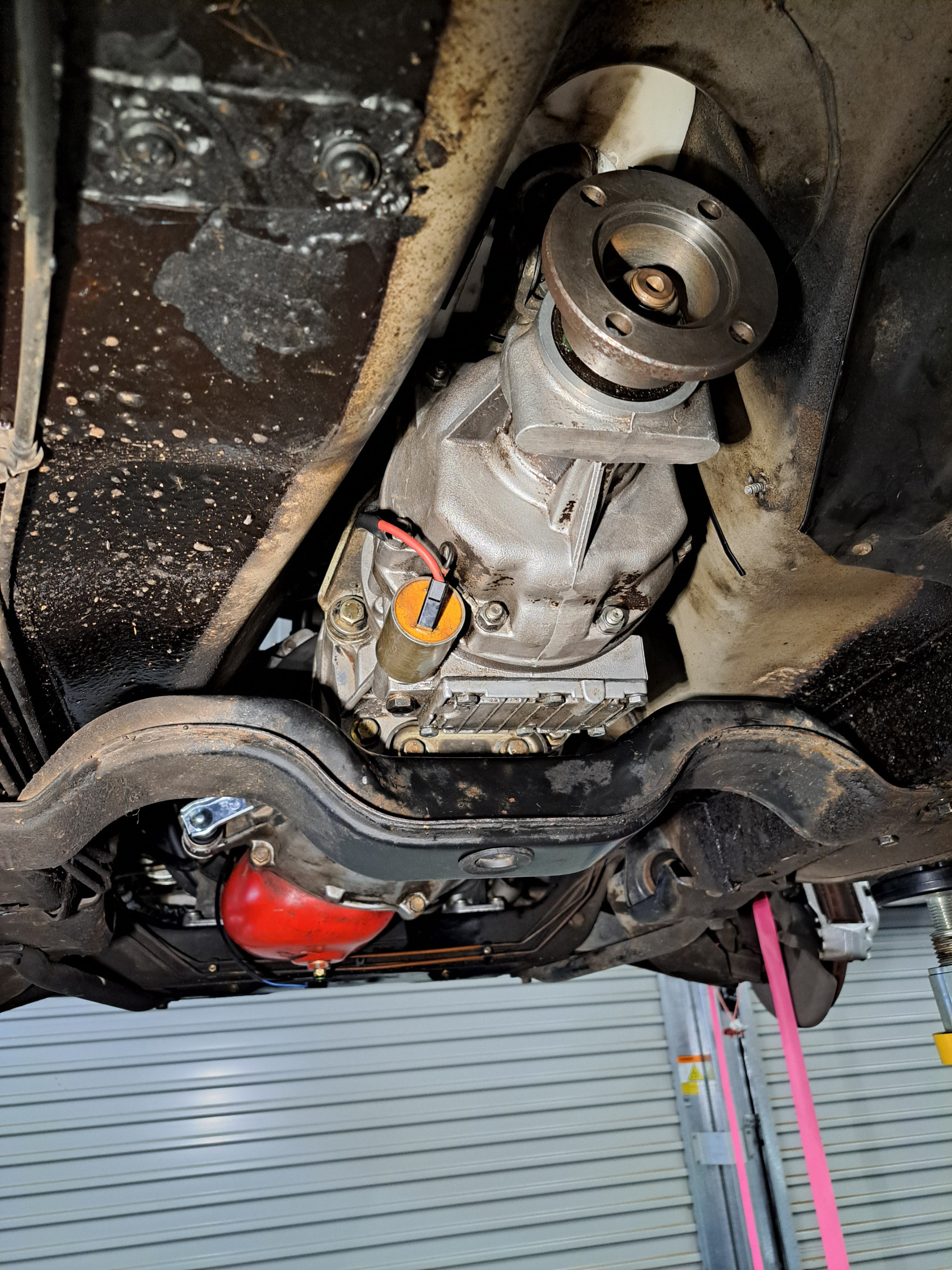
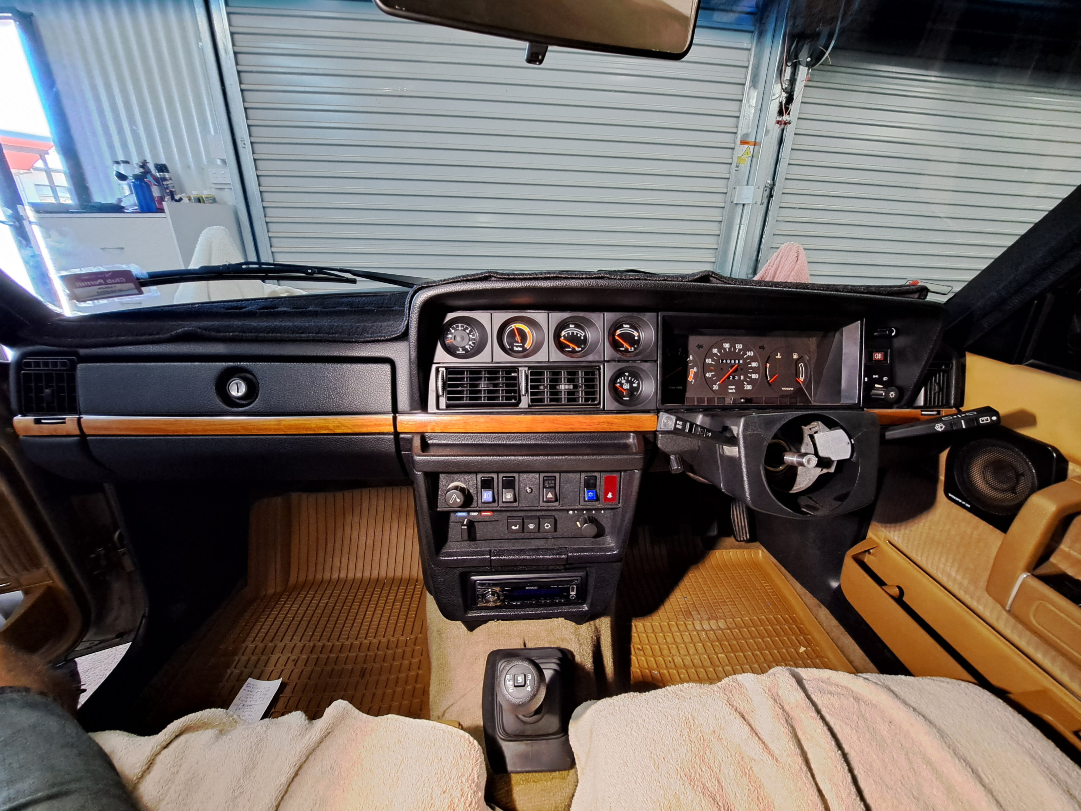
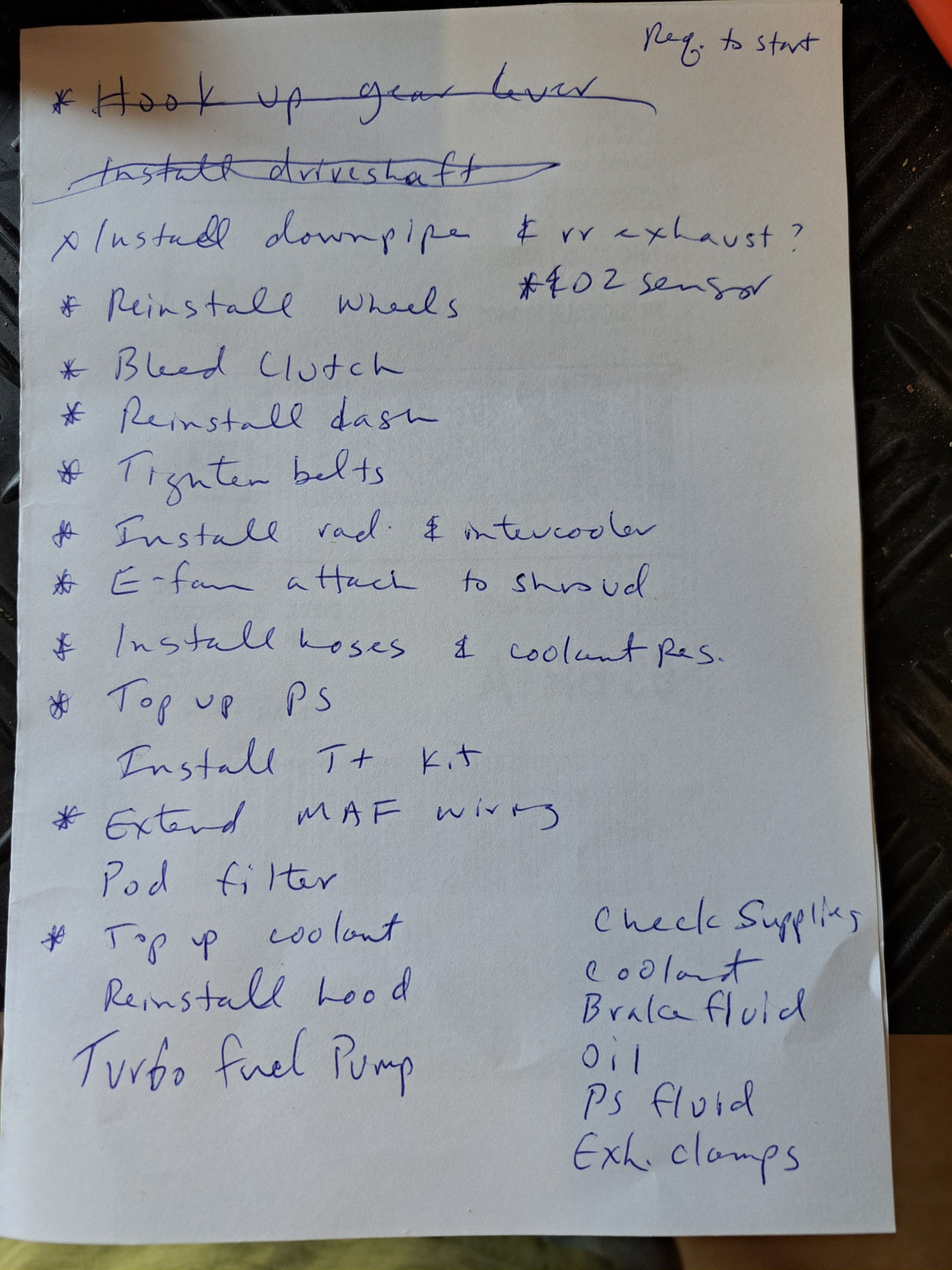
Next steps: connect the gear lever to the selector mechanism, install the boot, knob, switch and cap. Need to bleed clutch hydraulic system. Install drive shaft, downpipe, cat, exhaust, radiator/E-fan, intercooler, pipes, hoses, extend MAF wiring, etc, etc. Will need to work out what I'm going to do with air filtration. Possibly will just do a pod filter temporarily, but would like a proper airbox with cold air intake from under headlamp.
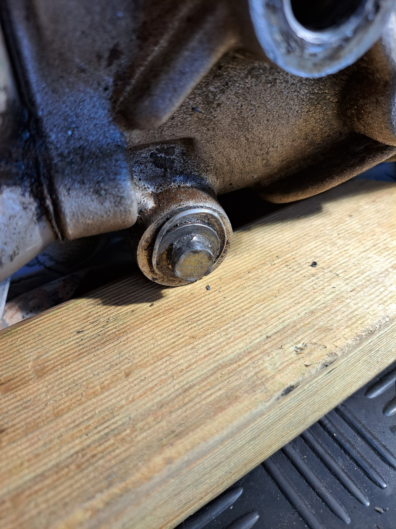
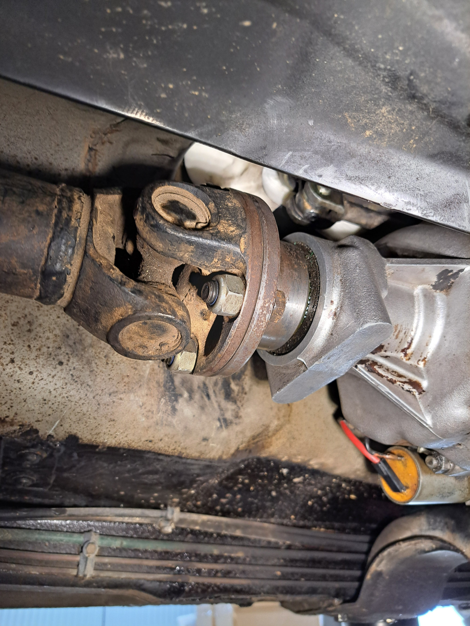
Got quite a bit done yesterday. Had similar issues with the gearbox driveshaft mating flange as I ran into on the yellow 245 project car. The bolt holes in the flange were slightly too small for the bolts…so had to drill those out, then the diameter of the area forward of the flange is larger so the large nuts wouldn't fit…had to install bolts with nuts facing rearward. Not sure what or when things changed, but Volvo did some strange things with these flanges and bolts over the years. I think I also had to take a bit of material off on the recessed area inside the flange to allow the driveshaft protruding part to slip in there, but I had done that months ago when I was test fitting the flange to the driveshaft front section. Also had to swap the good original 1991 centre bearing onto the short M46 driveshaft section as both M46 driveshaft sections I have in stock had bad bearings. I hadn't ordered a new bearing - DOH!
Also got the clutch bled, wheels & tyres reinstalled and shifted car forward (off the hoist) so we could get the dash and interior reinstalled.
Today we'll be working in the engine bay on hoses, wiring, fluids etc.
PS: Yes, I could have replaced the u-joint and cleaned and painted the shaft, but I'm NOT my dad (thank dog for that!)
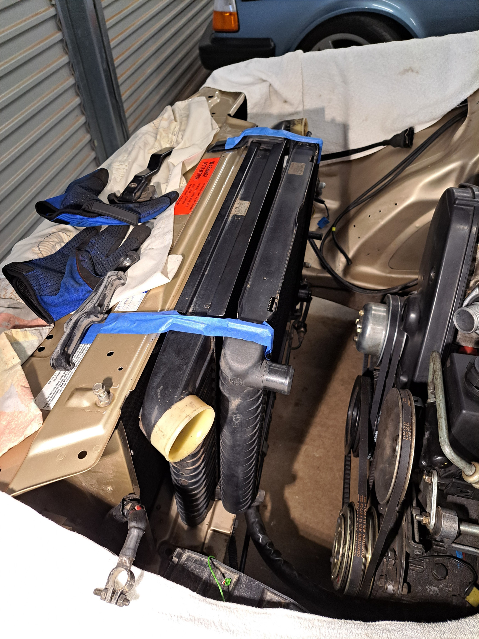
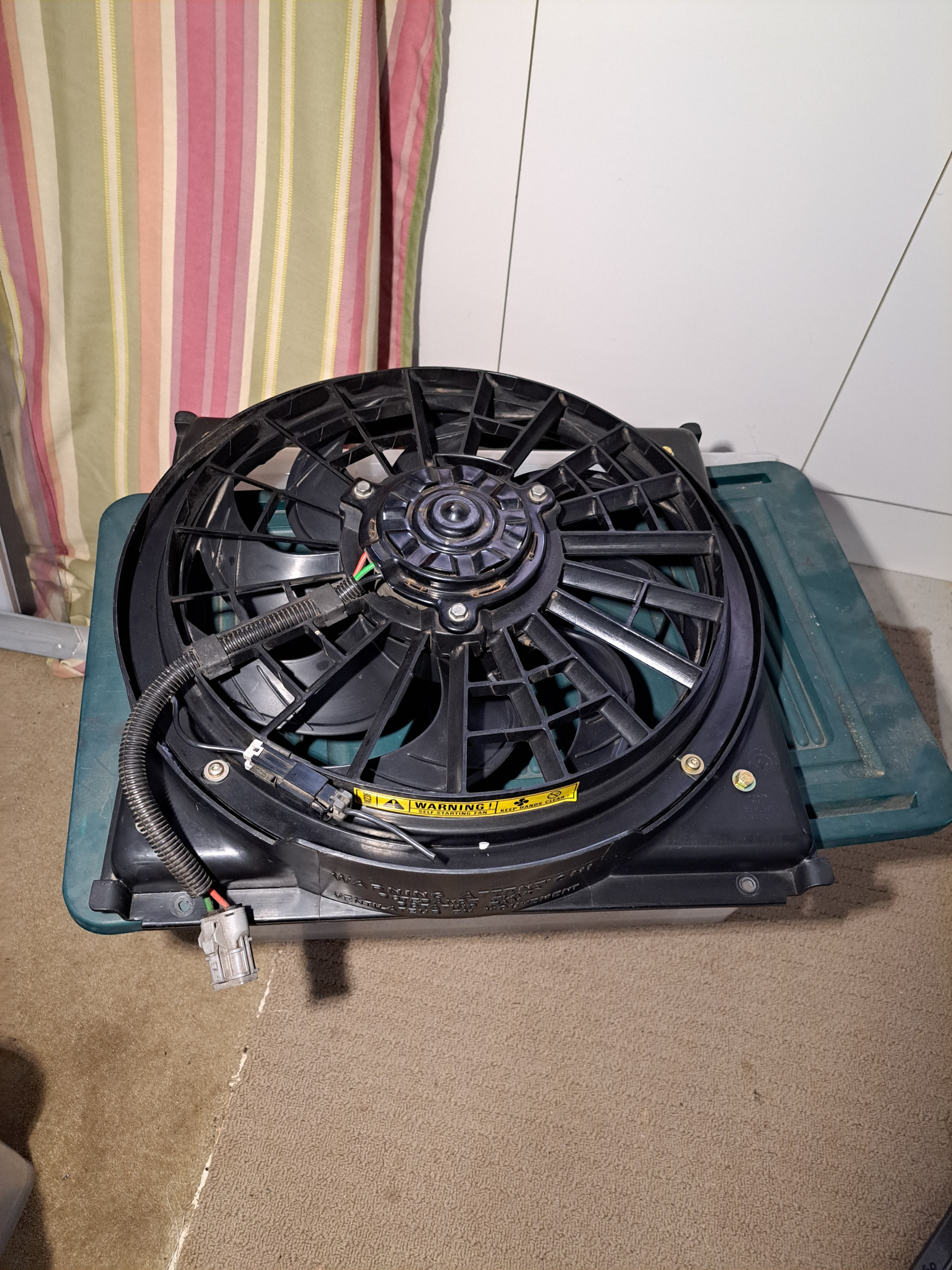
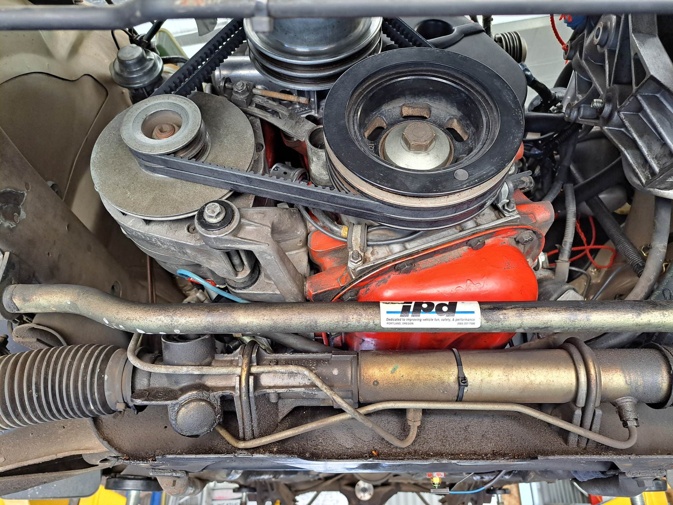
Got the belts tightened after swapping PS pump bracket adjuster (I've changed to the integral reservior pump set-up from a 93 240 so had to piece together the brackets to suit). Patched in a longer MAF harness and routed that over to where the MAF will sit. Got my 850 (?) fan mounted to the 740T shroud with an interfacing bit from the 850 shroud. Then put intercooler and radiator in position, only to find the brackets from the 740T would never be able to work (I thought you could just cut a notch in them for the bump in the 240 front panel, but the mounting surface is way too high on the 740 brackets). So, back to square one on that - looking at making one bracket from two (nose of 240 bracket and back end of 740T bracket). Really should cut and weld, but may see if I can overlap and join them somehow? Otherwise I'll just source an "expensive" set of genuine 240T intercooler/radiator mounts (probably easier given I have more money than patience at this point in life!) Then put radiator shroud and fan in place and DAMN, the fan is just about touching the water pump pulley. So back to the drawing board on that (maybe some spacers to move the fan slightly closer to the radiator will be an easy "fix"). Still haven't decided what I will use to control the fan - I have a Davies-Craig fan controller, but haven't looked at instructions yet to see whether it's capable of doing 2 speeds. Need to make up an airflow block-out panel to close gap between LH side of intercooler and radiator support (where the OE oil cooler would sit, and may sit in future?) Fun, games and plenty of cursing today!