Glad you're happier with where it's at now in terms of ride and rate compared to your starting point with the coilovers you have - bouncing around some emails with you and working through it to get to an improvement over what you're started with is the fun/interesting part of doing what we do.

Shoot me an email when you can - I have an idea for the front end that might help too.

18 days later
October 2022 - Wasted Spark Install

Amongst other things that were going on at the time, I occasionally took a break to work on some electrical things, like the Wasted Spark install.

I'd already installed a chip in the EZK unit but I'd bought a Buchka wasted spark board from cflomoto last year, and was waiting for the opportunity to install it.

I took a night off from wrenching and did some soldering instead, wiring in the WS board into the EZK. Potted the joins on the EZK and WS board with hot glue to stop damage from vibrations/movement.

I used a 4-pin microphone connector for the two-channel ignition output and also for the arm/set features of the launch control, if I feel like implementing that down the line. Note, if you're going to use a microphone connector in this location, get a right-angle female connector as space is tight where the EZK mounts.

I'd also purchased a 2x2 coil for $3 on closeout at RockAuto, and got a 960 ignitor module at the same time. The ignitor is a Huco item, and the coil is... unknown. So unknown that when I found a genuine new Bosch motorsport 407 coil for $69 I smashed the Buy It Now button on it so I wasn't worrying so much if I'd end up stranded somewhere because of being a tightarse. The other coil will be a spare.

With the parts all ready, I started to plan it out. I picked up a heatsink and started fabbing up a plate to mount to the drivers side strut tower support where the ignitor and relay for tacho drive would live. Here's what it looked like installed, later:

I then started measuring, designing and then 3dprinting a coil mount for the rocker cover. Remember: measure 3 times, print 4 times, then change your mind about where you want to mount it.

I decided after the first couple of mockups that I'd mount the coil on the rear most valve cover holes. I'm keeping the dizzy in place because it doesn't hurt to have it there while I source the head plug and make a bracket to hold it in. Also, I could easily revert back to coil and dizzy should this fail and leave us stranded at the side of the road.

I hadn't found many details online about how to modify a relay for the tacho drive. Because I was planning on keeping the original ignition stage in place, I'd just need to figure out how to remove the contactor in a relay I had spare, and we should be in business. So I cracked one open, found the part of the relay that goes 'click' and started hacking it out. Removing the above seems to have worked. Hooray for saving all those relays from someone's old car alarm install..

I used some 4-core wire with a sufficient heat rating to hook up the coil and the new ignition module, and hooked up the relay to the old coil wiring.

I was chuffed that it worked first crank, and even the tacho worked. It's so nice when things work out like you hope.

The verdict? Immediately noticed that it seems more eager, and revs cleaner, as hard as that is to convey in writing. Hooray.

Awesome. How good are those Bunnings standoffs!

I reported the same results when doing the wasted spark conversion on mine. Much smoother and revs cleaner.

However for simplicity I used an NA6 MX5 J702T ignition module as it drove the tacho directly!

I also wired up the launch control on mine, worked great!

  • deNs replied to this.
    nugget_940

    Awesome. How good are those Bunnings standoffs!

    I reported the same results when doing the wasted spark conversion on mine. Much smoother and revs cleaner.

    However for simplicity I used an NA6 MX5 J702T ignition module as it drove the tacho directly!

    I also wired up the launch control on mine, worked great!

    Wait what, bunnings have standoffs you can buy in store? That would've saved me some time. I ended up buying them from here because that appeared to be the easiest source at the time. Oh well!

    What did you use for a switch for the clutch, if that's what you did? or did you just set it up to a couple of momentary switches on the dash perhaps?

      deNs

      https://ozvolvo.org/discussion/comment/215173#Comment_215173

      Wait what, bunnings have standoffs you can buy in store? That would've saved me some time. I ended up buying them from here because that appeared to be the easiest source at the time. Oh well!

      What did you use for a switch for the clutch, if that's what you did? or did you just set it up to a couple of momentary switches on the dash perhaps?

      https://www.bunnings.com.au/pinnacle-m6-galvanised-coupler-6-pack_p1101062

      I used a spare lightbar push on/off switch on the dash as the set rpm switch and then a small momentary button in the centre console where the heated seat switches would usually go as the arming button. Nice and close to the shifter.

      Also while I was doing the wasted spark I did the ezk +3 degrees of timing mod as well and added that to a toggle switch on the dash.

      October 2022 - Speakers, etc.

      I was never hugely happy with the speakers I installed in the drivers doors, but then I didn't really do the best job and they were cheap JVC speakers so you can't expect miracles. The original 940 door speakers now live on inside a Raspberry-pi-powered internet radio at home, and it made me wonder why I ripped them out in the first place. They work pretty excellently!

      So anyway, a sale came up and I picked up two pairs of Rockford Fosgate Prime R1525x2 speakers for the front/rear doors. They're nothing fancy, but the hope is that with these, some sound deadening and sealing around the speakers that I'd have a chance of getting some better sound from those.

      I went through a fair bit of trial and error with how I'd mount the speakers to the door skins, but ultimately I went and mounted them behind the 3D-Printed adapter (100% infill, and drilled out the holes to suit the speakers - https://www.thingiverse.com/thing:4636676 ) to mount them to the original holes in the doors. 

      There was sufficient space behind the speaker so it didn't foul on the metal on the door, though because of where the terminals on the speakers are, they're mounted upside down. Just don't look too closely or you'll see the Rockford Fosgate logo isn't the right way up!

      The rears are still hooked up to the aftermarket headunit (Pioneer DEH-X4750BT), and the fronts are hooked up to the circa-2007 Jaycar Response 4x50W amp in the boot. The dash tweeters were disconnected as they are now covered by dashmat and were making it a little too harsh with treble.

      the original RCAs I had hooking up the amplifier were slightly too short and I ripped the centre pin out of one in the amp when I lifted up the boot floor when hastily packing to move interstate a few months prior, so I took the opportunity to try to fix it. Thanks to the wonder of the internet, a heated up pin stuck into the centre of the broken pin allowed me to pull it out.

      I had disassembled the guts of the amp to try to push it out from behind, but turns out this was the only option. You need to heat up the tool/pin you're using with a lighter before it'll melt into the centre of the broken pin. Thanks again, internet ;)

      Aliexpress 5 meter RCAs replaced with a pair of Aerpro MX550 cables (5.5m).

      I had purchased a kit of butyl-based 'Car Builders' sound deadening for doing the doors and inside of the boot, and a fairly old Dynamat extreme bulk pack I've had lying around for years was used for the majority of the boot area. I used some Jaycar response acoustic mat in the area behind the speakers in the doors to further help with sound. Thus far I've used the sound deadener on:

      Door skins of all 4 doorsBoot skinSpare wheel wellUnder rear seatInner rear wheel arches

      I need to pull the carpet and do the trans tunnel at some stage too, to see if I can quieten that M90 noise if possible. I understand why they simply had to use a DMF now!

      Overall it sounds okay after some tweaking, and it'll probably sound better again once I figure out how I want to hook up my old Invisabass 6.5" sub in the boot. I'm thinking to make a frame that mounts underneath the false floor, that has hinges to allow for the spare tyre to be accessible while still being able to lift the false floor separate to the sub. Future project!

      I also want to replace the fairly large amp with something I can fit under the side rear pockets if possible, to make more space for the sub under the floor potentially. For now, it sounds OK with some minor EQ tweaking so I can comfortably listen to some swedish metal while sitting inside my box of swedish metal.

      September - November 2022 - Air Conditioning

      This is a fairly long one.

      Back when we travelled to Tassie in 2021, I dropped by BMG and picked up the r134a parts from a 94' 940 sedan that would give me the bulk of items that I'd need to reinstall the aircon into the car. 

      After some searching, ringing around and discussing with people in the industry about how I was going to go about refitting the aircon, it turns out that my plan of attack was going to be something like:

      New parts for the system:

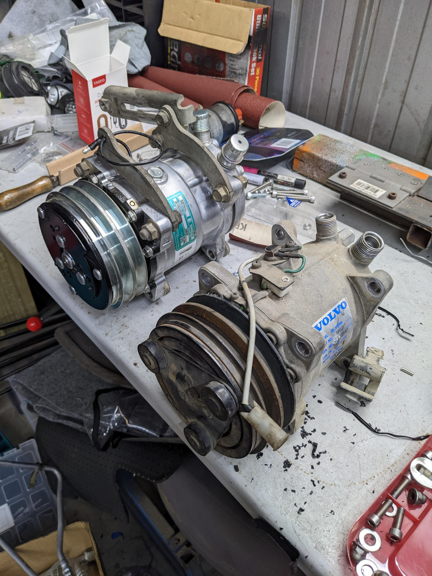
      Compressor (Sanden SD5H14)Condensor (Nissens - already got from Skandix)Accumulator Orifice tube (turns out it uses a GM part or they share the same part)

      Things that need to be remade/fixed:

      Flexible lines (crimps were splitting on both, hoses marked 1993)

      Things that are second-hand that I'd use:

      All hard lines and mountsEvaporator (already in car)...that's about it.

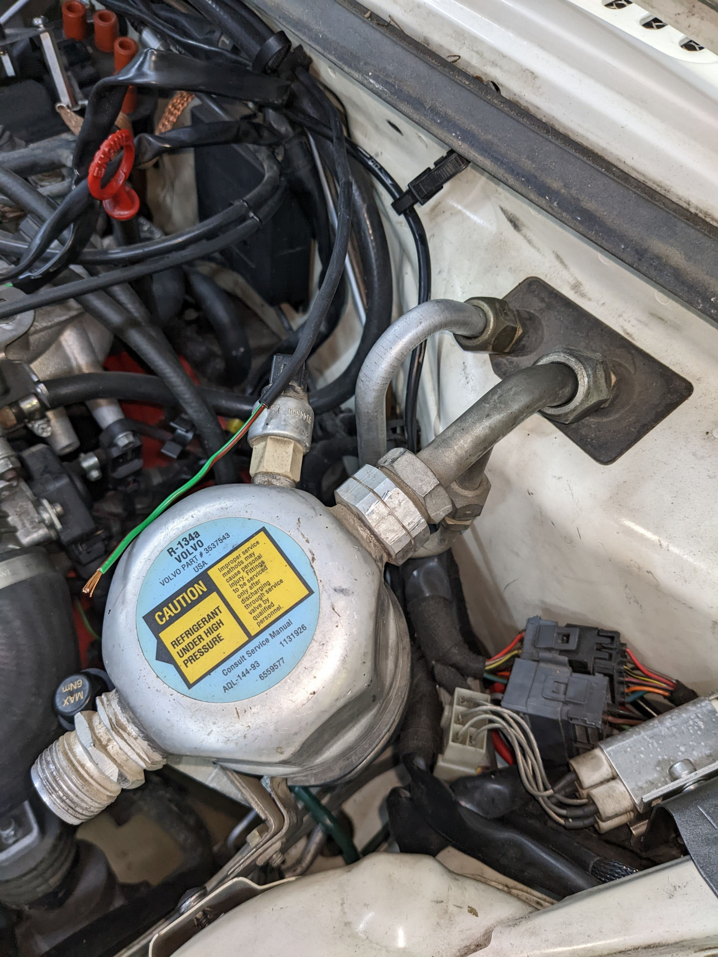
      I'd bought the wrong Accumulator from Skandix years ago, not realising the differences between the R134a and the R12 one. At least it wasn't an expensive mistake. Main difference is on the suction line of the R12 accumulator it uses a reverse thread, but is otherwise identical. D'oh.

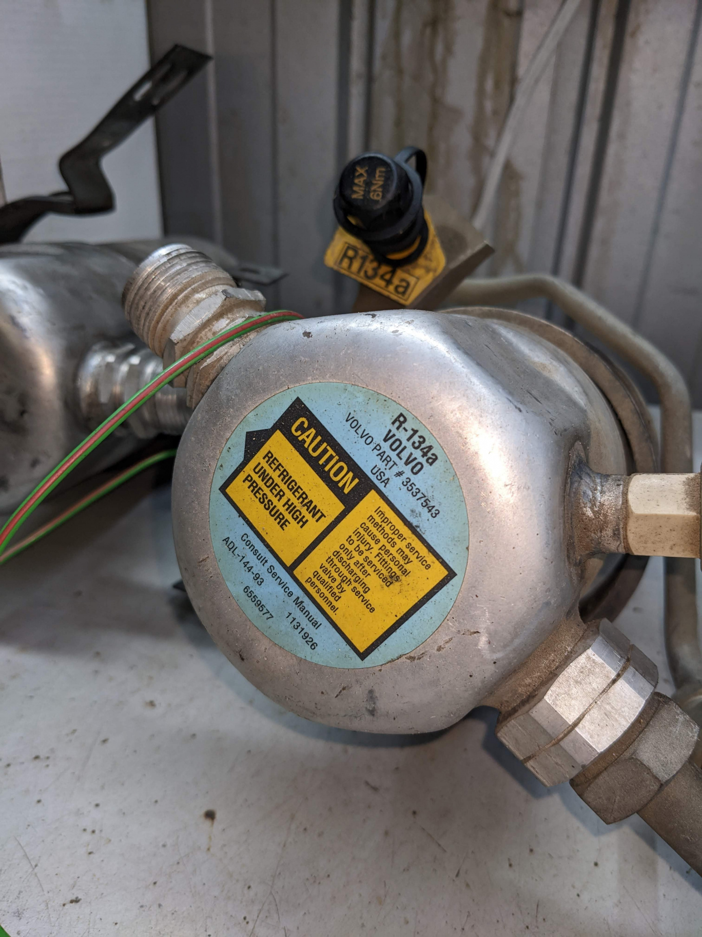
      Correct R134a accumulator is the Jayair RD7100 which is a direct r134a swap for Volvo part 353743. Was around $50 new.

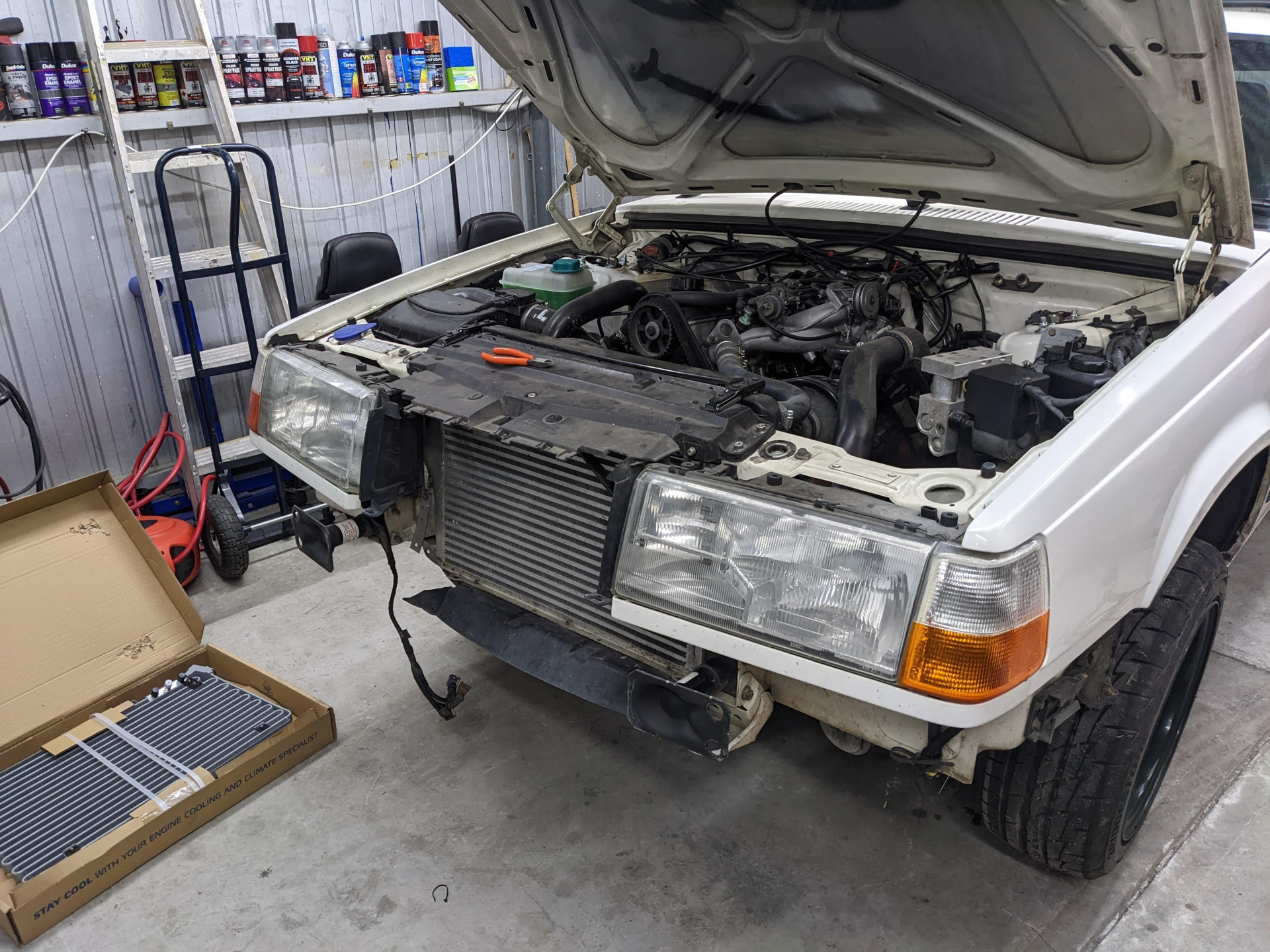
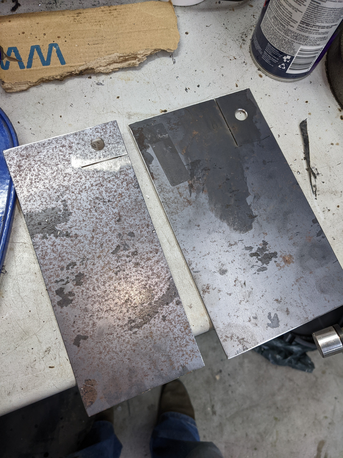
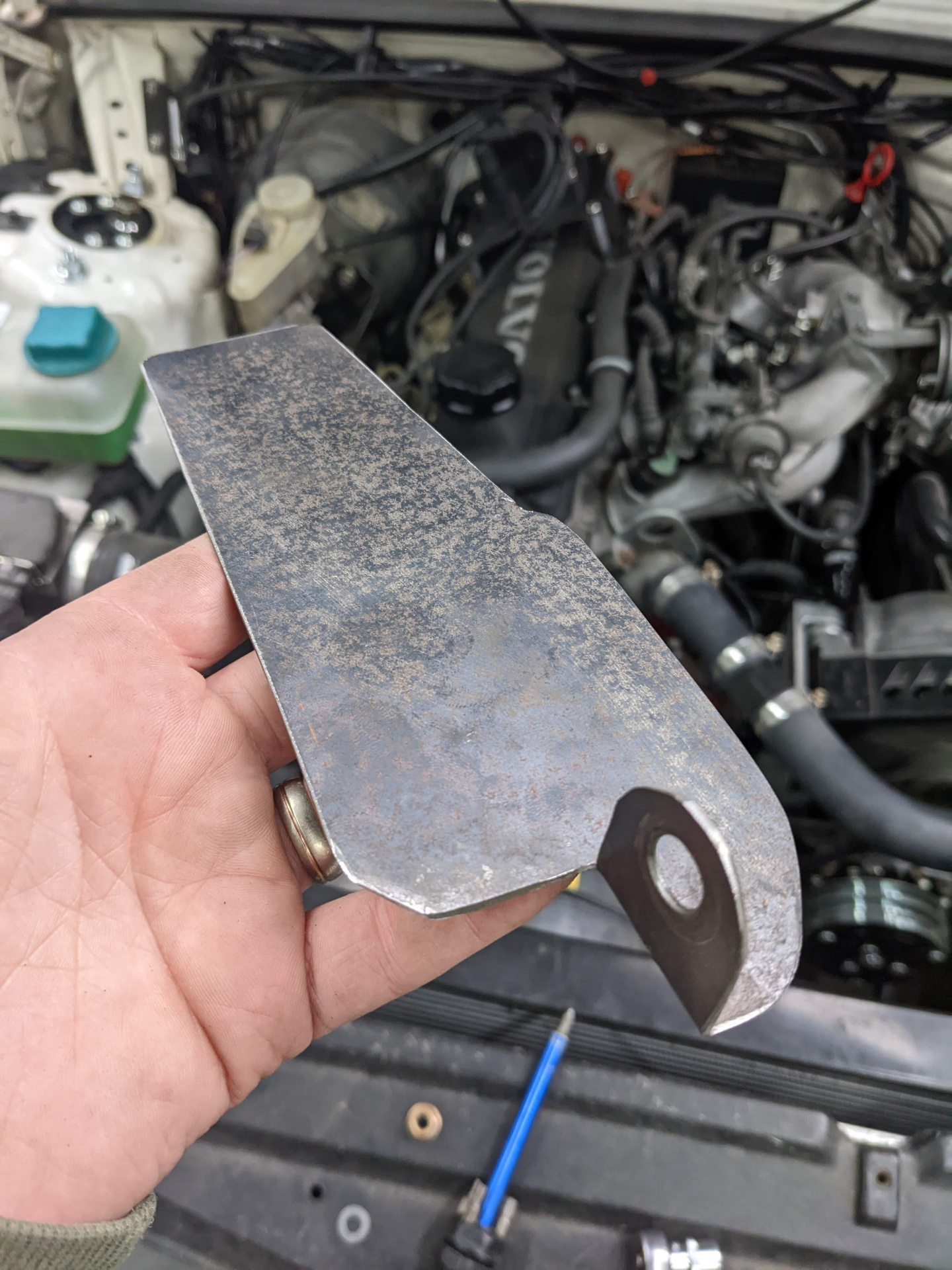
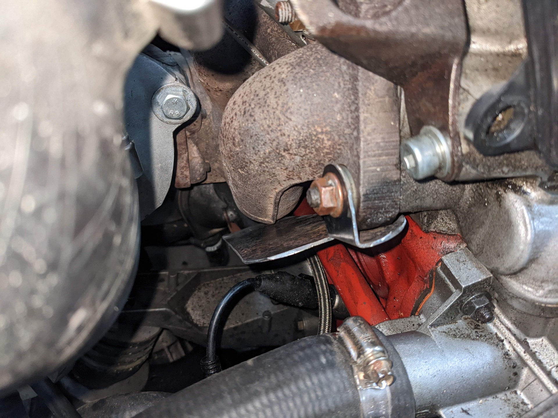
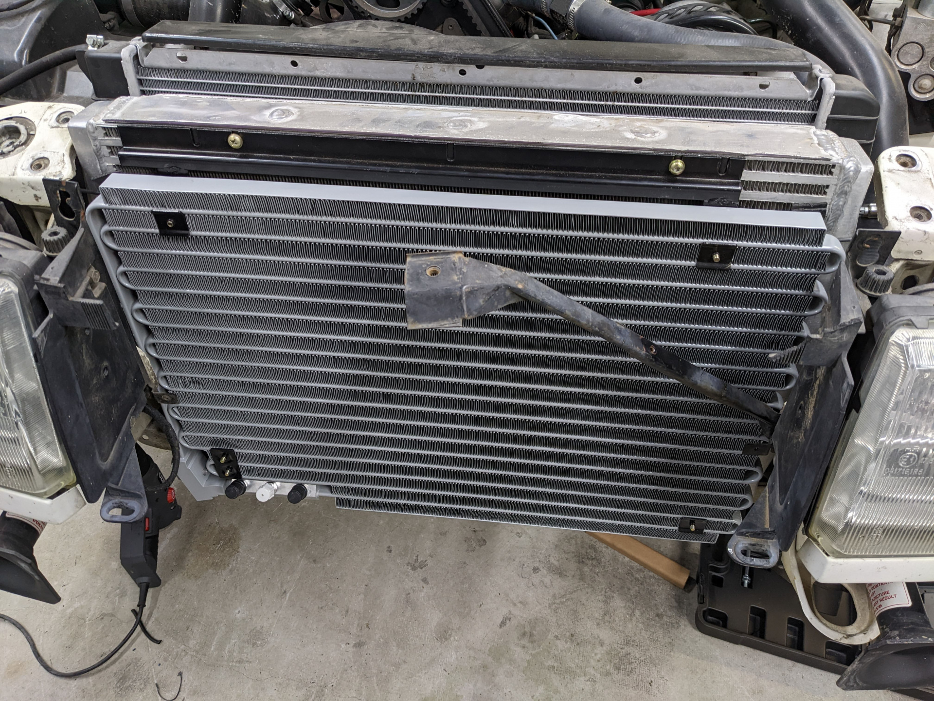
      I started fitting up the condensor ahead of time, as I knew with the bigger intercooler it was likely to be a challenge, as I had no idea how they mounted. Thankfully, I got the right condensor as they're different between turbo and non-turbo but the shroud I had was to suit an N/A like what I pulled everything off. 

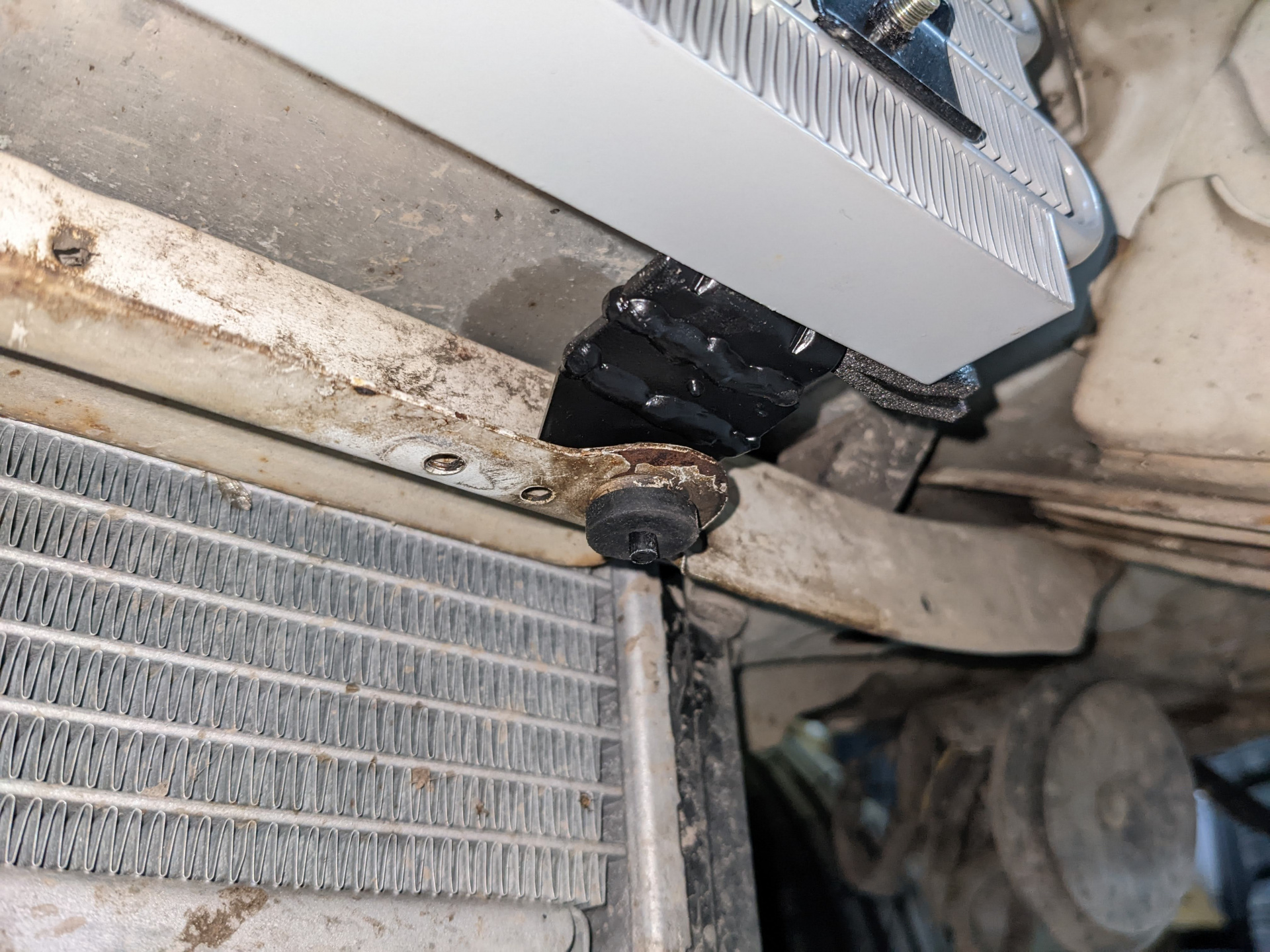
      I had to modify the mounts as the intercooler sat further forward than the original one would have because it's so thicc. Picked up a couple of rubber grommets to suit the mounting holes in the chassis to the condensor mounts from Clark Rubber. Works perfectly.

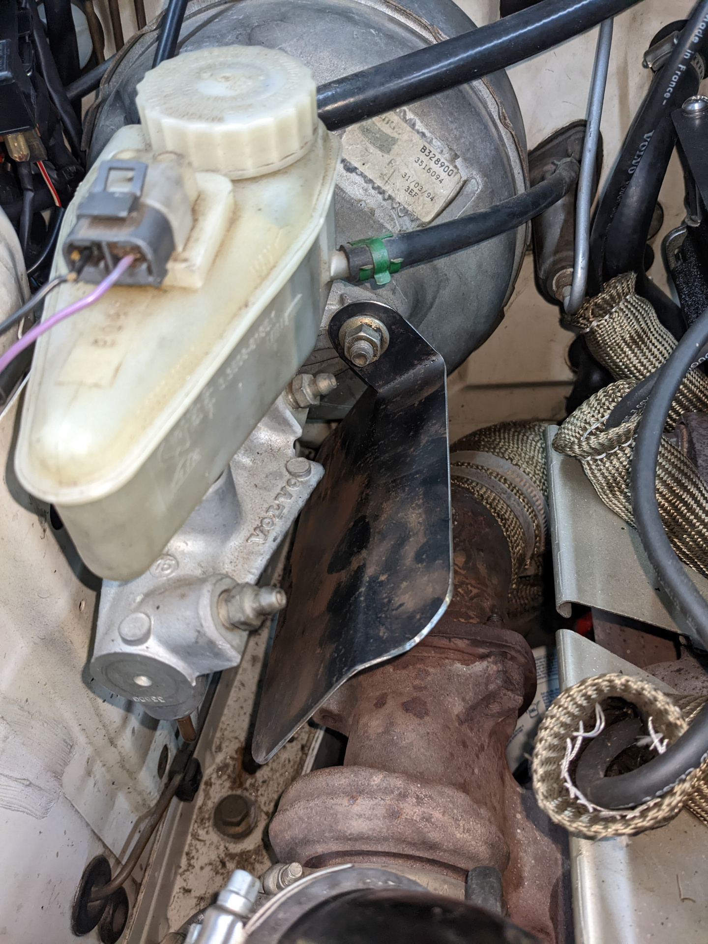
      With the condensor mounted up, I turned my attention to the rest of the items. I'd spoken with a workshop who did only aircon work in September, to try to get the ball rolling well before summer came. I ended up organising to get a new Sanden compressor through them, and they would make some new flex hoses to hook up to it. In the meantime I took one of the hard lines in that had the orifice tube mounted in it, to get that replaced as well. It's a $5 part and is vital to the functioning of the system, so it'd be silly not to here.

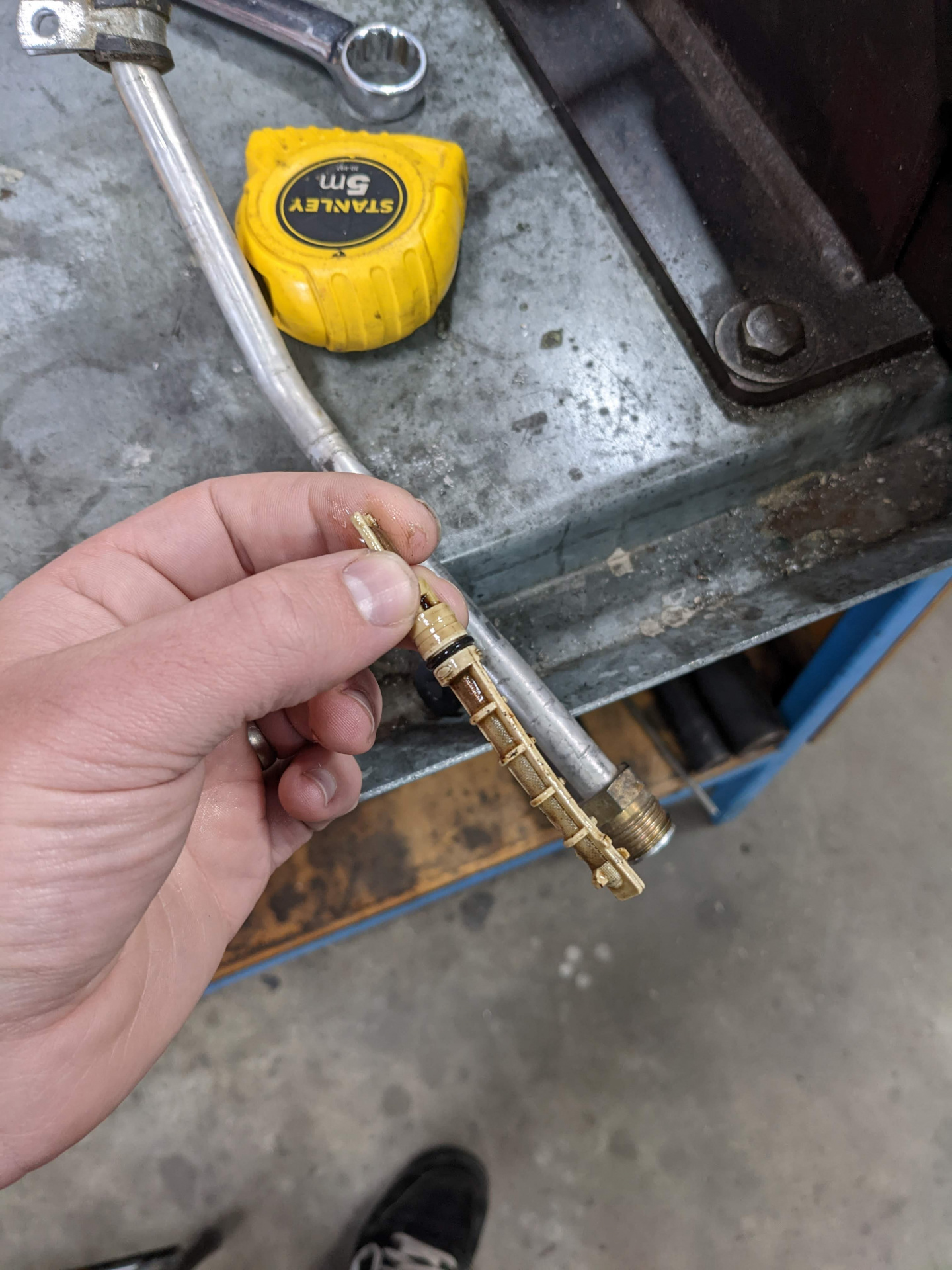
      Turns out the orifice tube pulled from the lines from the car I pulled parts from at BMG had the orifice tube installed backwards and was really wedged in there. Lucky I replaced it! Replacement was apparently the same part number as a GM one, so they thankfully had one on hand.

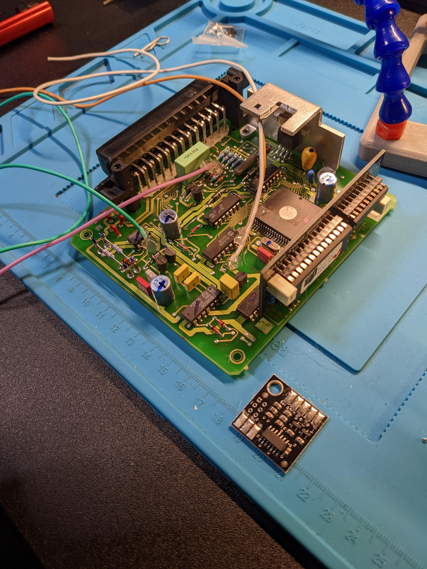
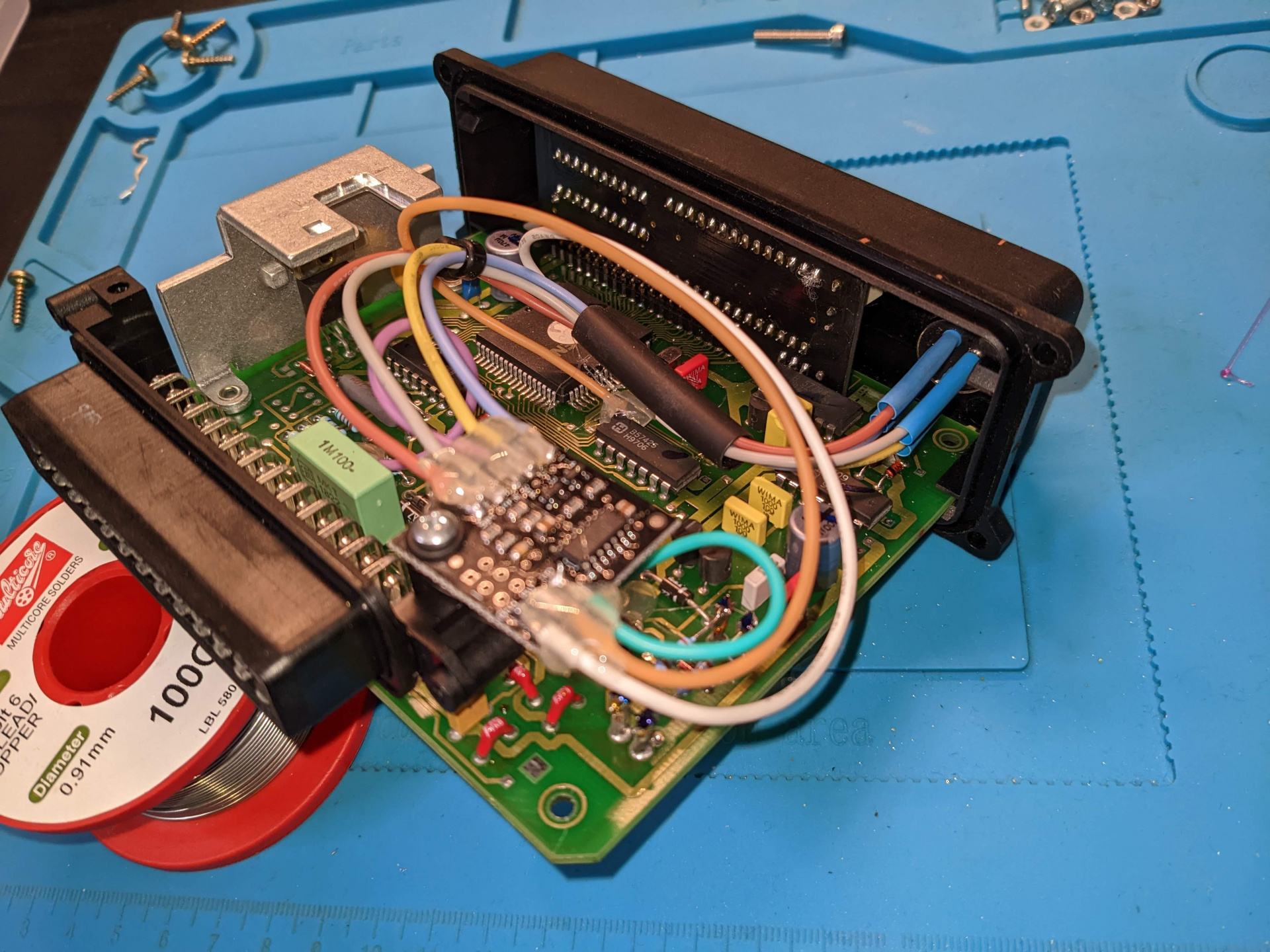
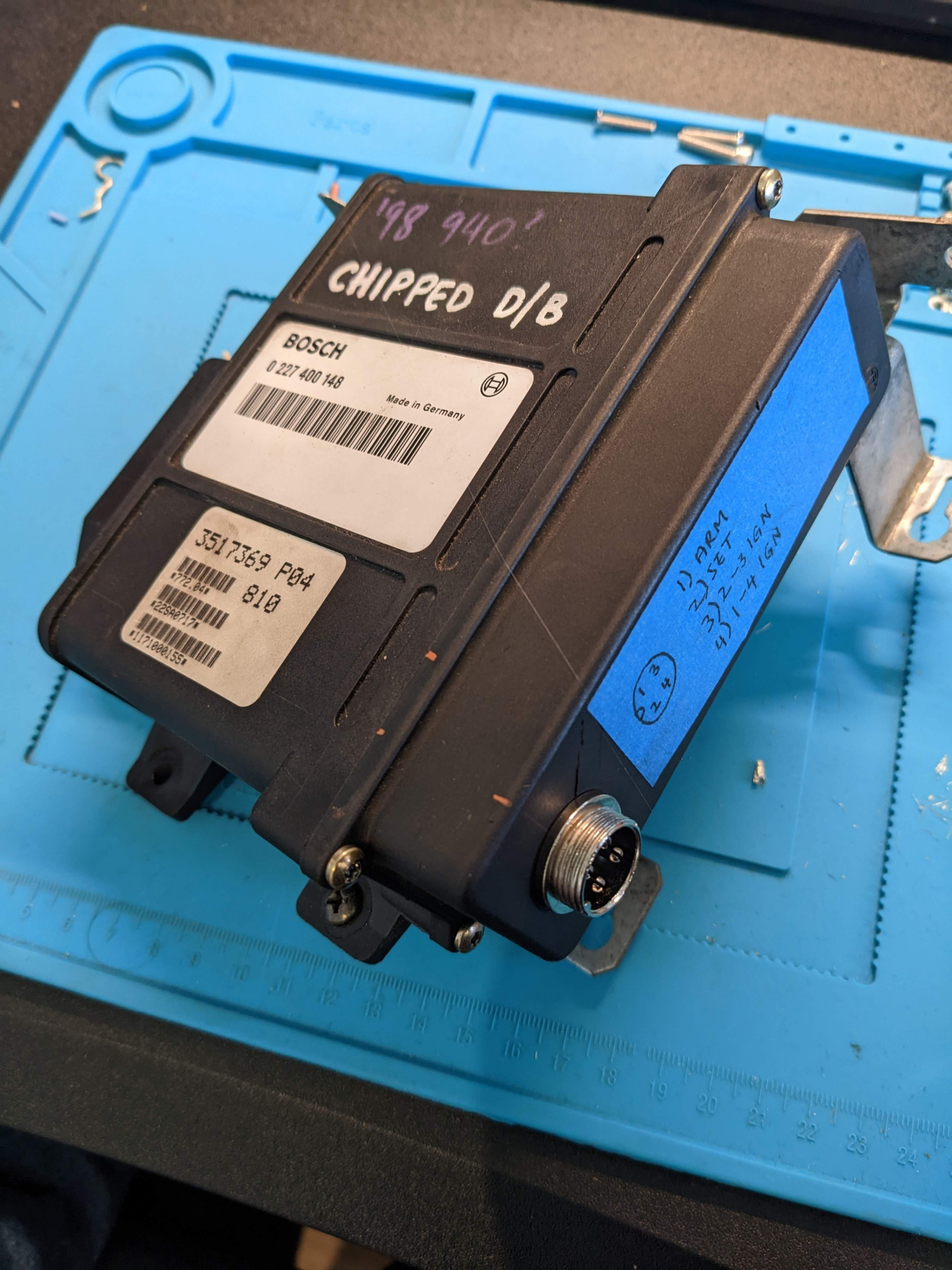
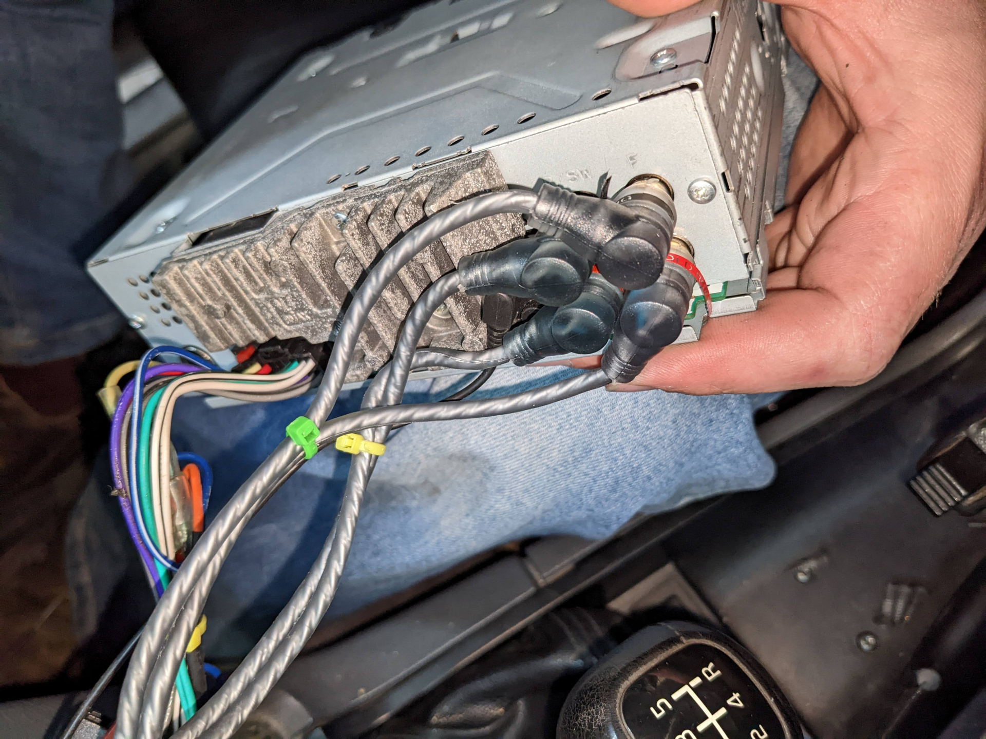
      While the hoses were being made up I turned my attention to the electricals. The guys at the shop advised me of what state I should have the system in when it comes time to charge it, and I got stuck into the wiring diagrams.

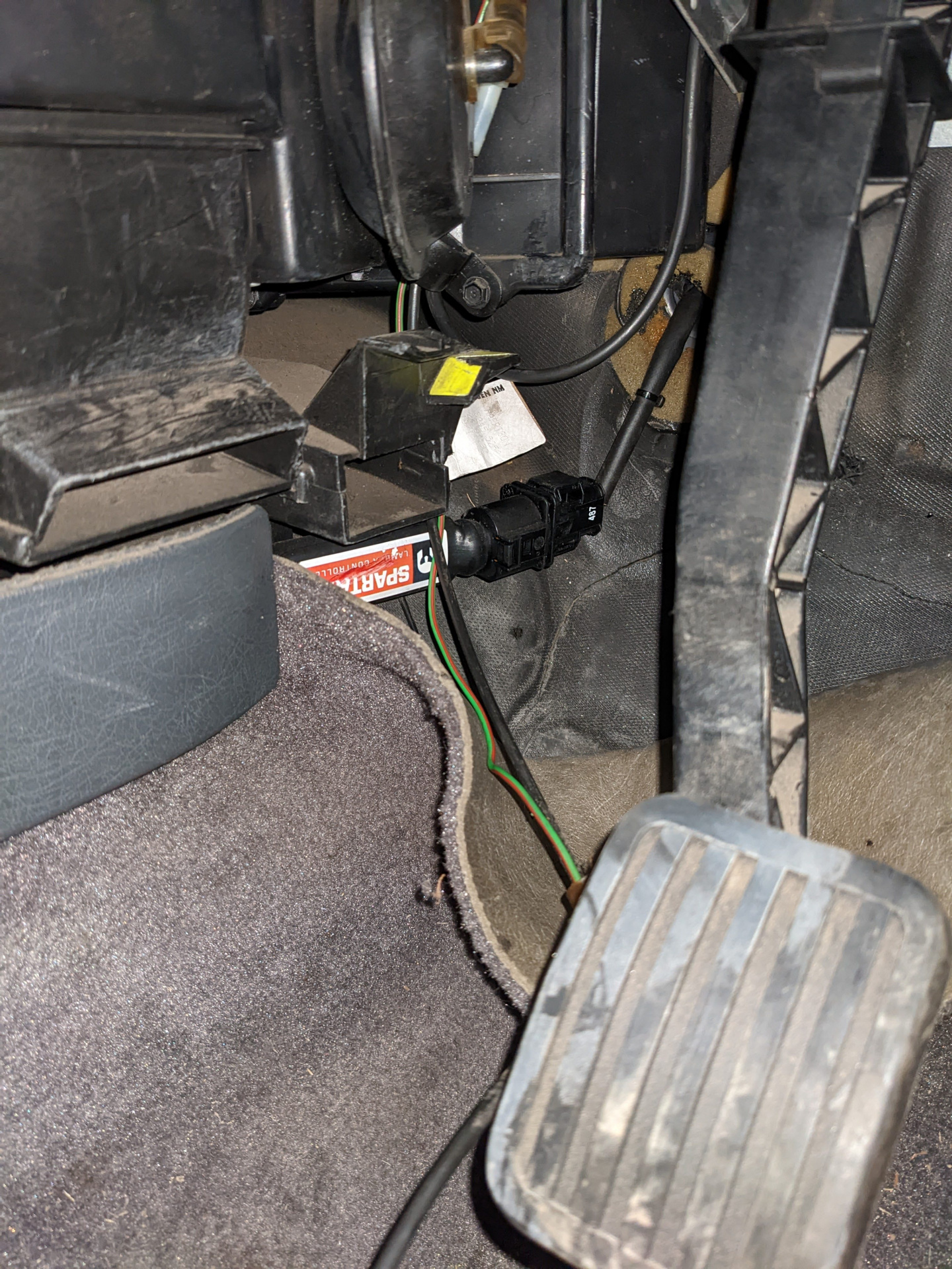
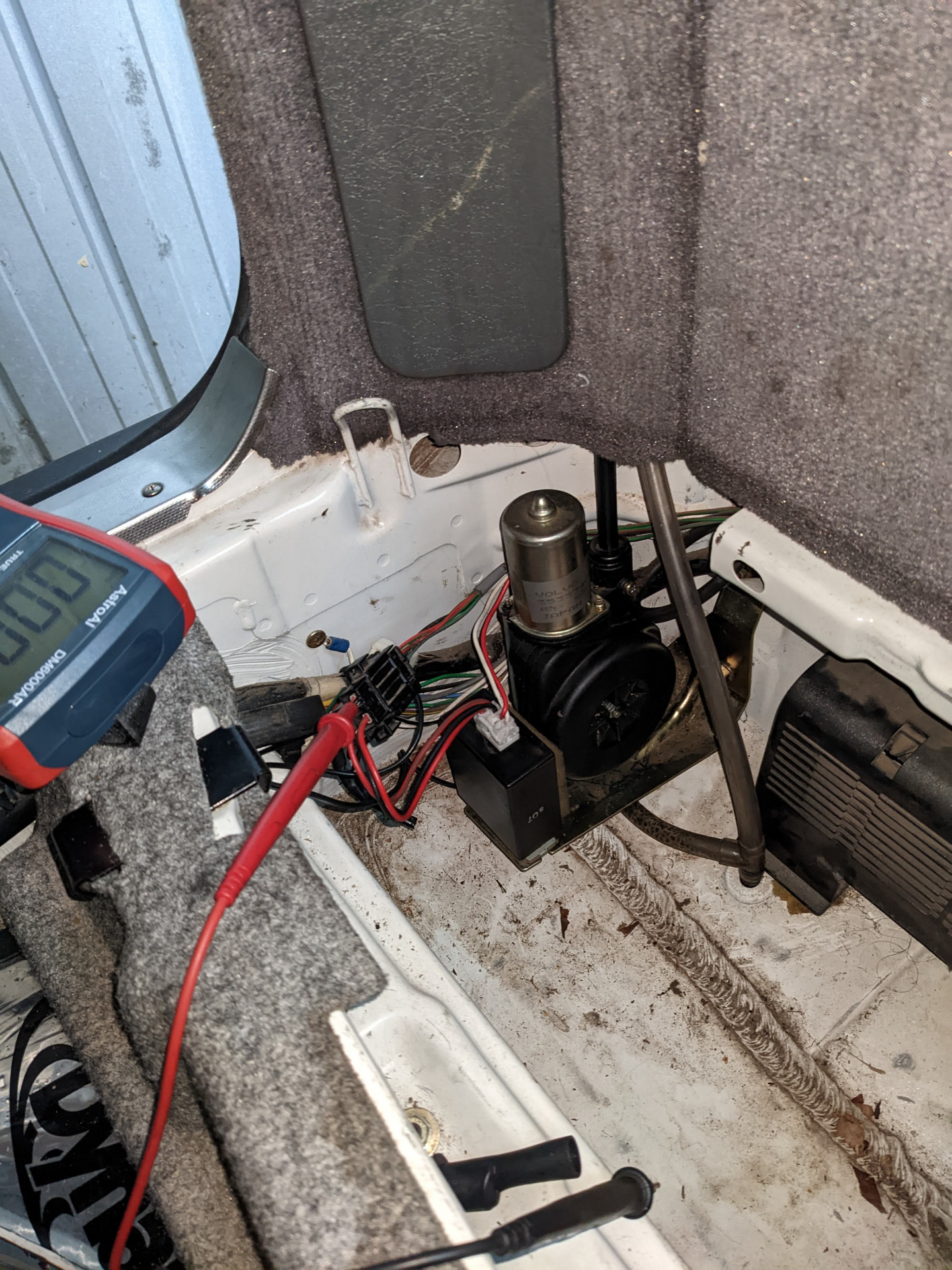
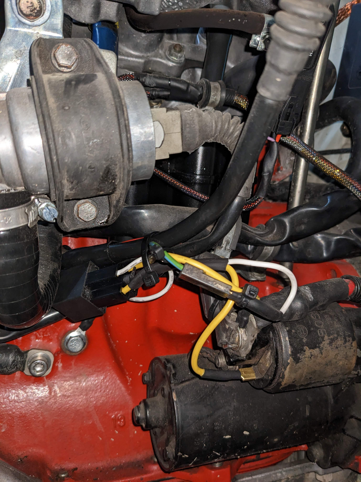
      First I had to find the wire from the HVAC dash control unit that goes directly to the low pressure sensor without any connectors, and I found that underneath the drivers side carpet, long ago sealed and discarded by myself who at the time didn't realise its significance. I then started testing to see if I got voltage at that line when aircon was turned on. Nope, 200-300mV fluctuating at best.

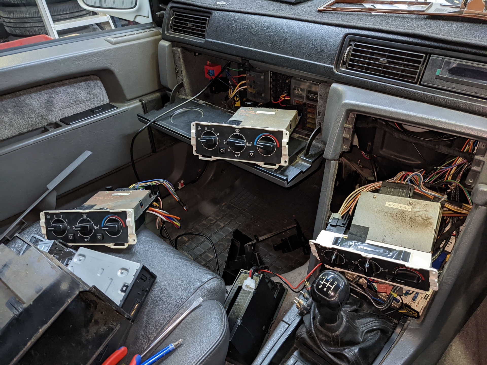
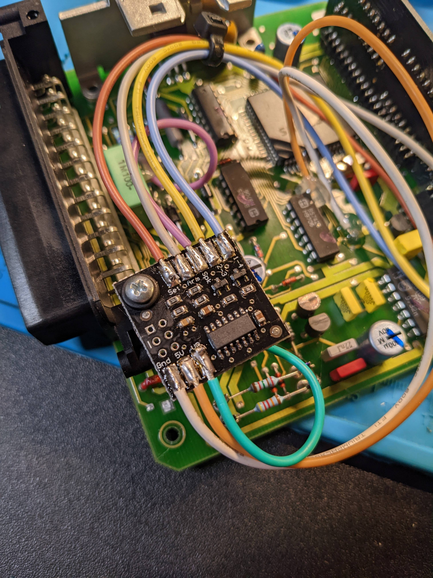
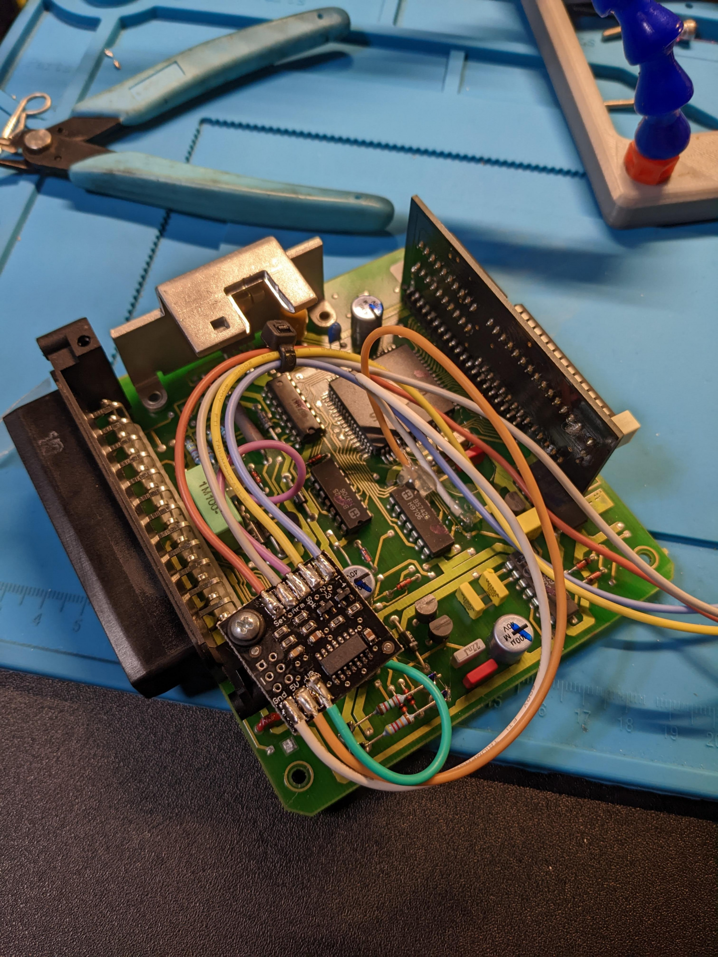
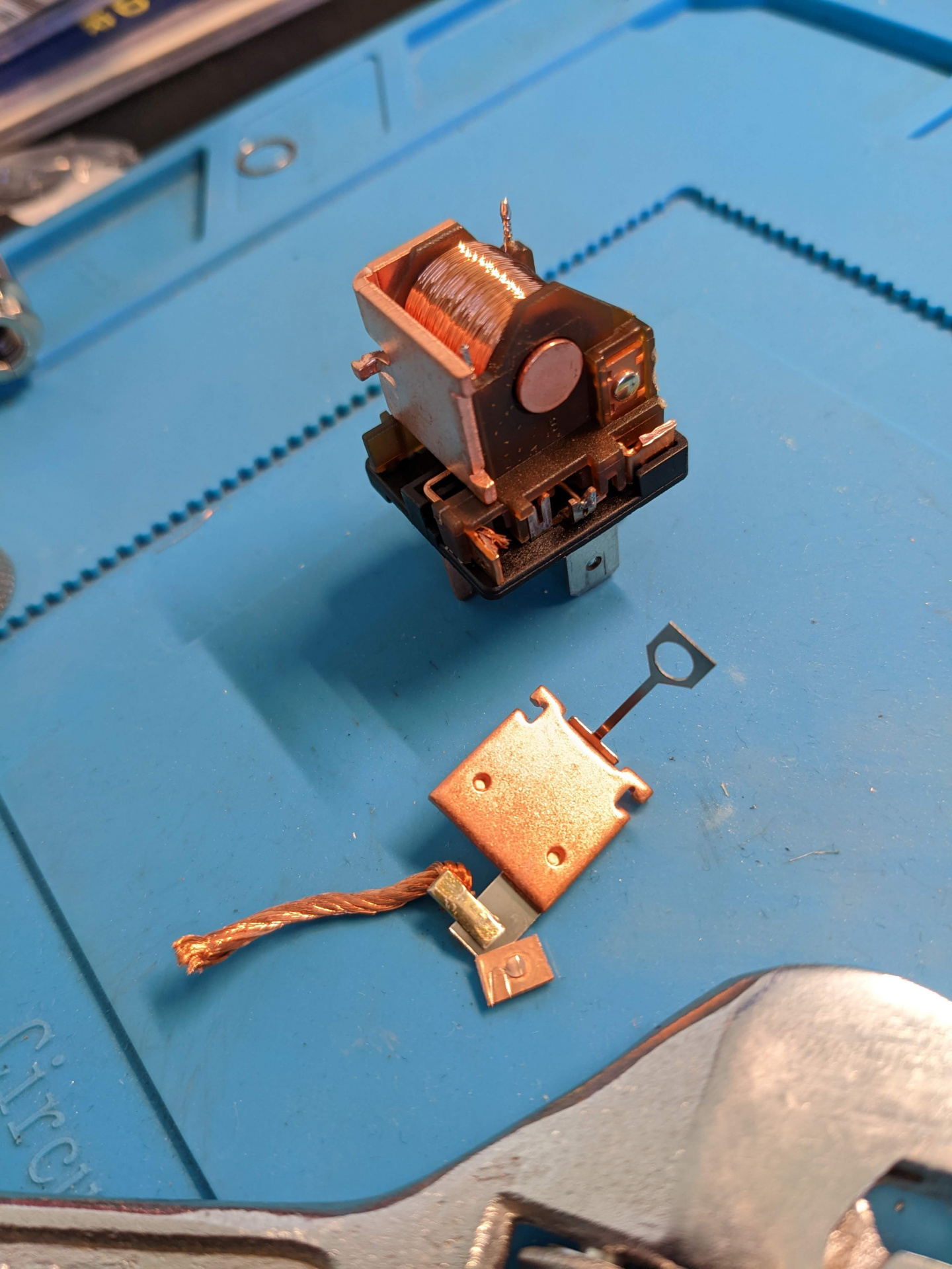
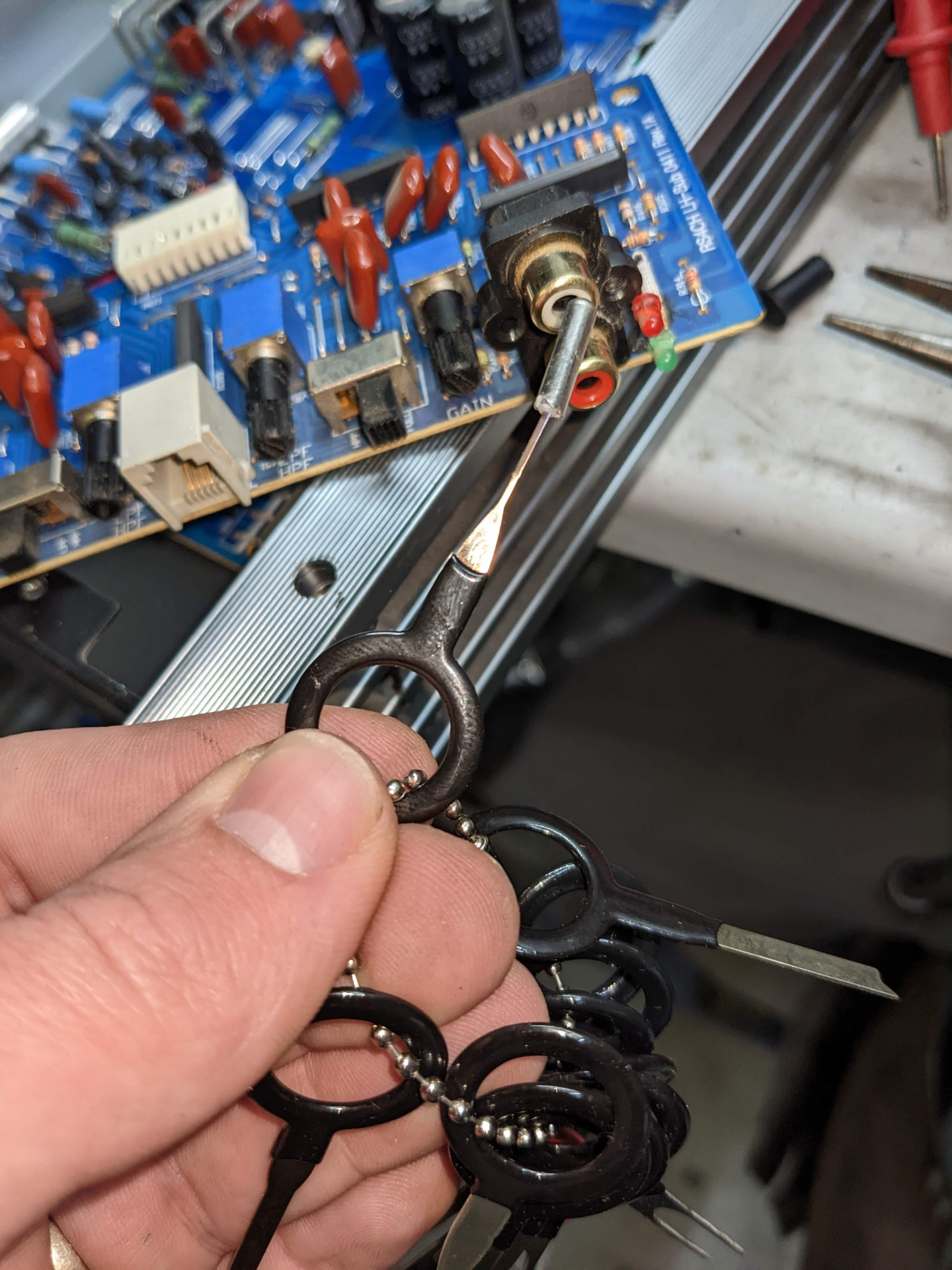
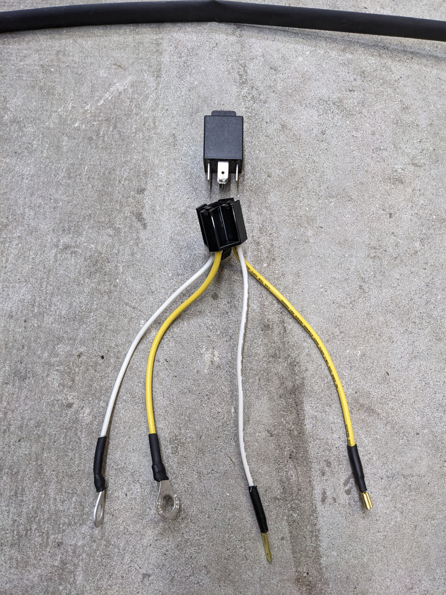
      I had 2 other spare control units, but after some reading and testing, it appears they all had the same result. I broke out the soldering iron, resoldered the joint on the relay on the PCB that commonly fails, and tested. BAM - 13v solid. Did the repair on the other 2 as well so now have 3 working units, so I got to work of running the wire properly again with parts of looms I had spare or got from the donor.
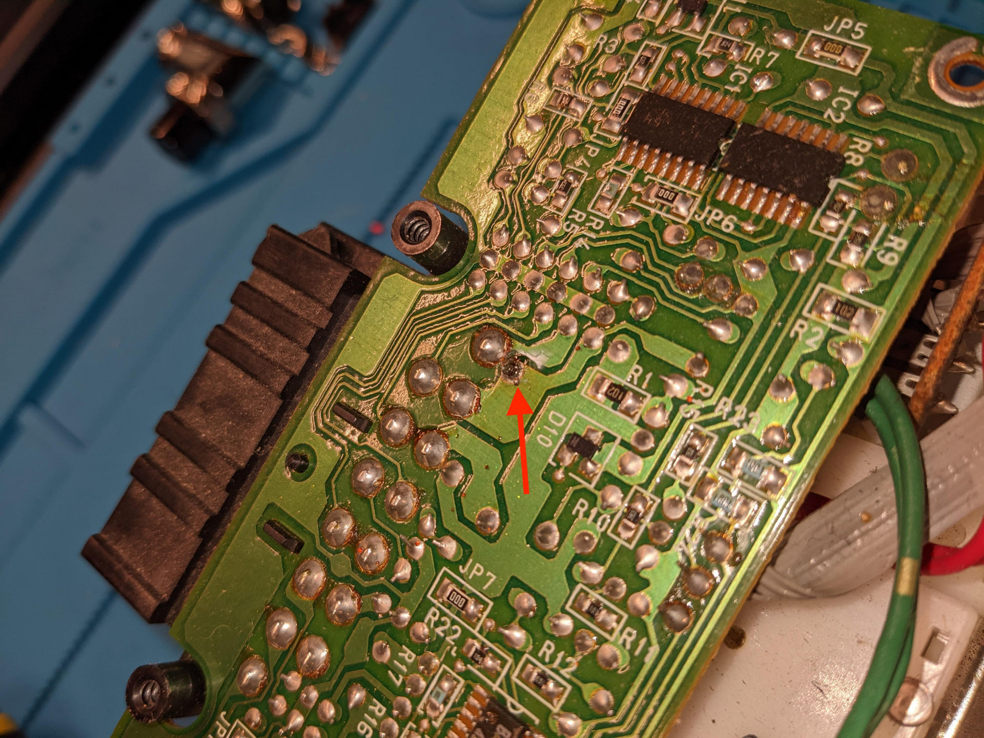
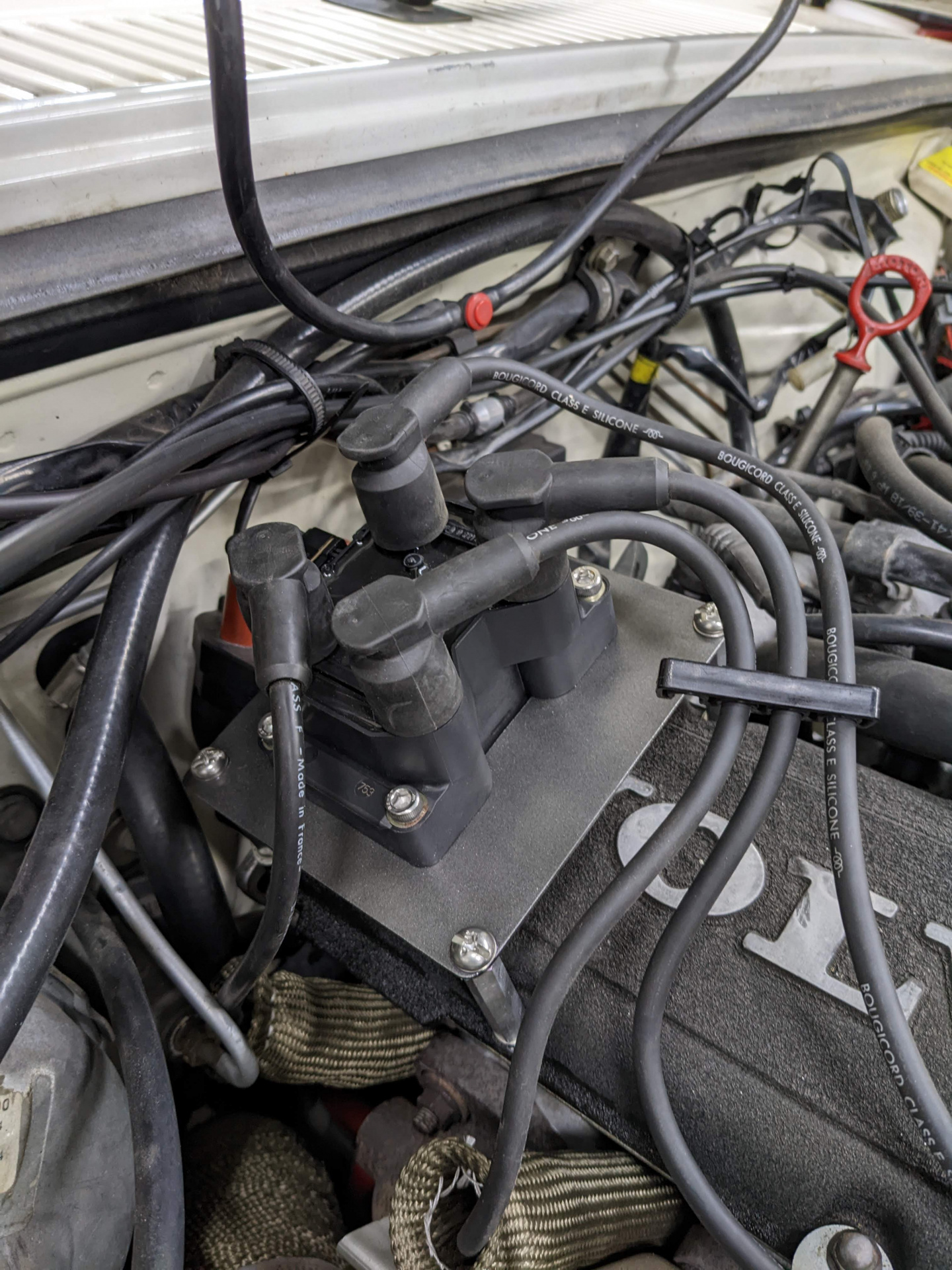
      That's the one.

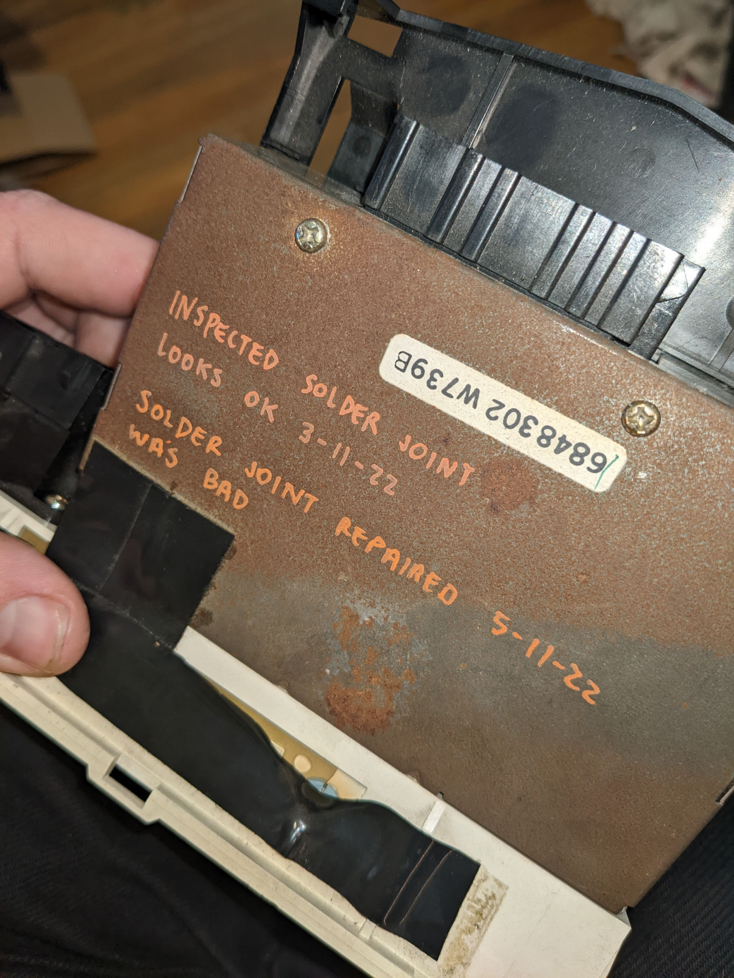
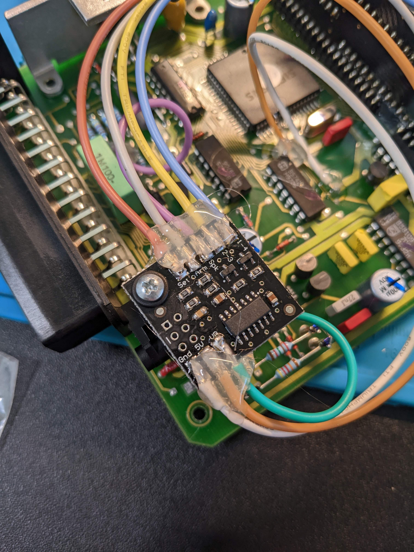
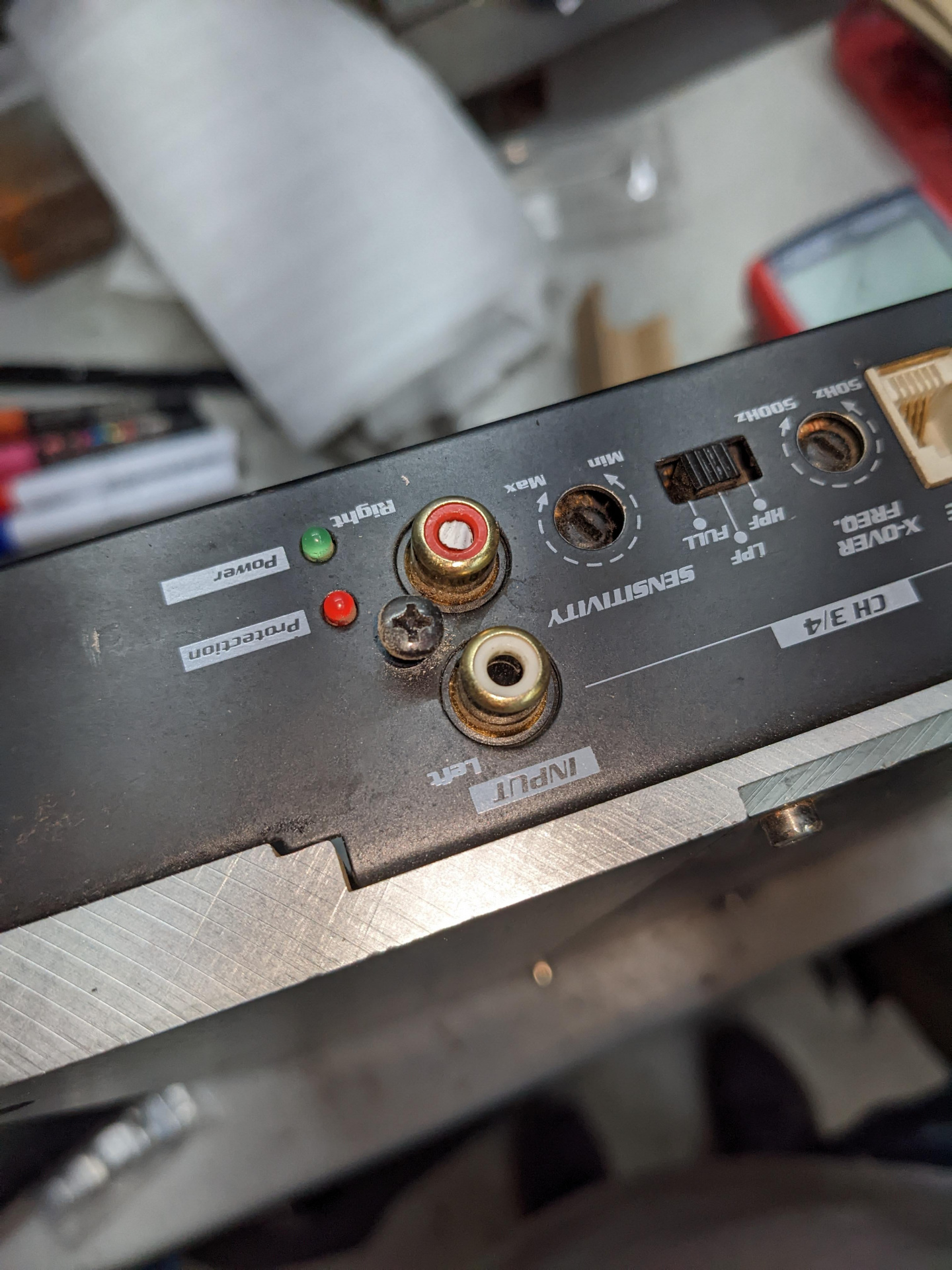
      Just 'cause it looks okay, doesn't mean it was...

      Wired up a new weather-pack single pin connector for the compressor and tested it out with some jumper leads to short out the high/low pressure switches to confirm battery voltage at the compressor lead. Working!

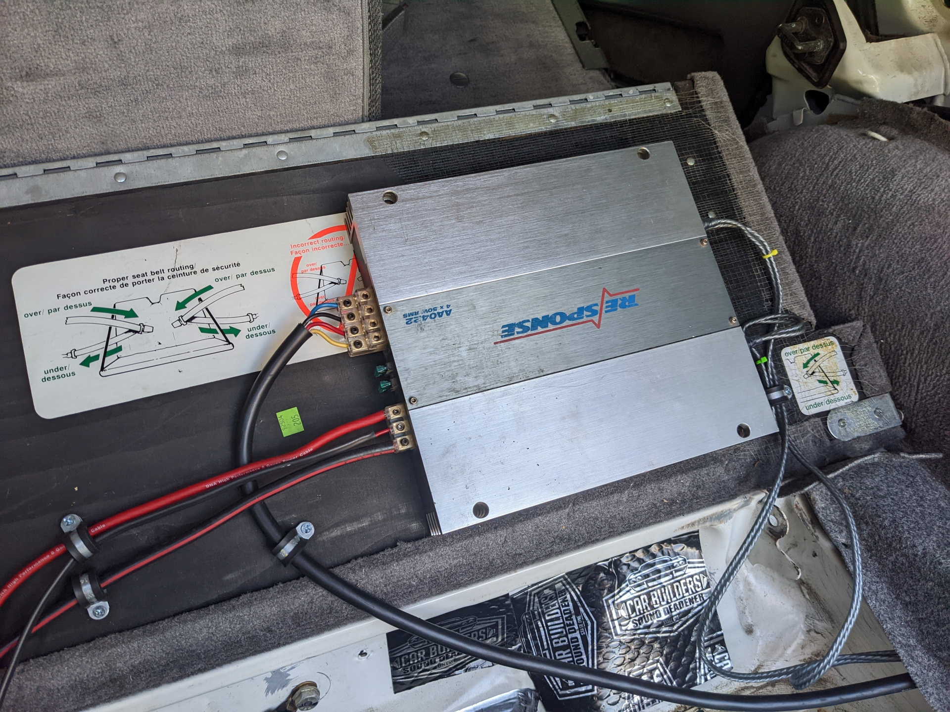
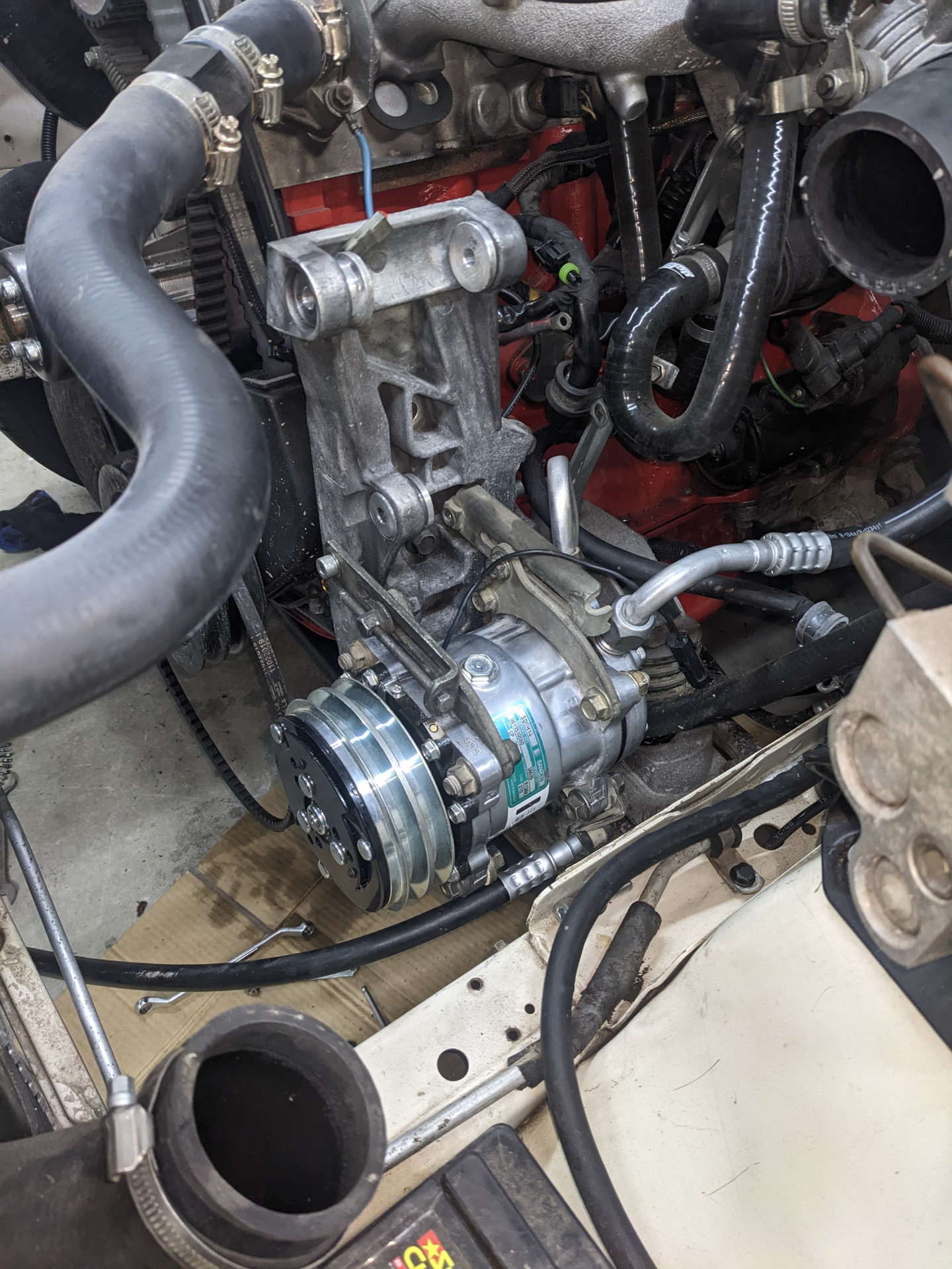
      Got the Sanden compressor and new lines ready to go in, and I'd start getting everything else into place to make sure I wouldn't have issues. 

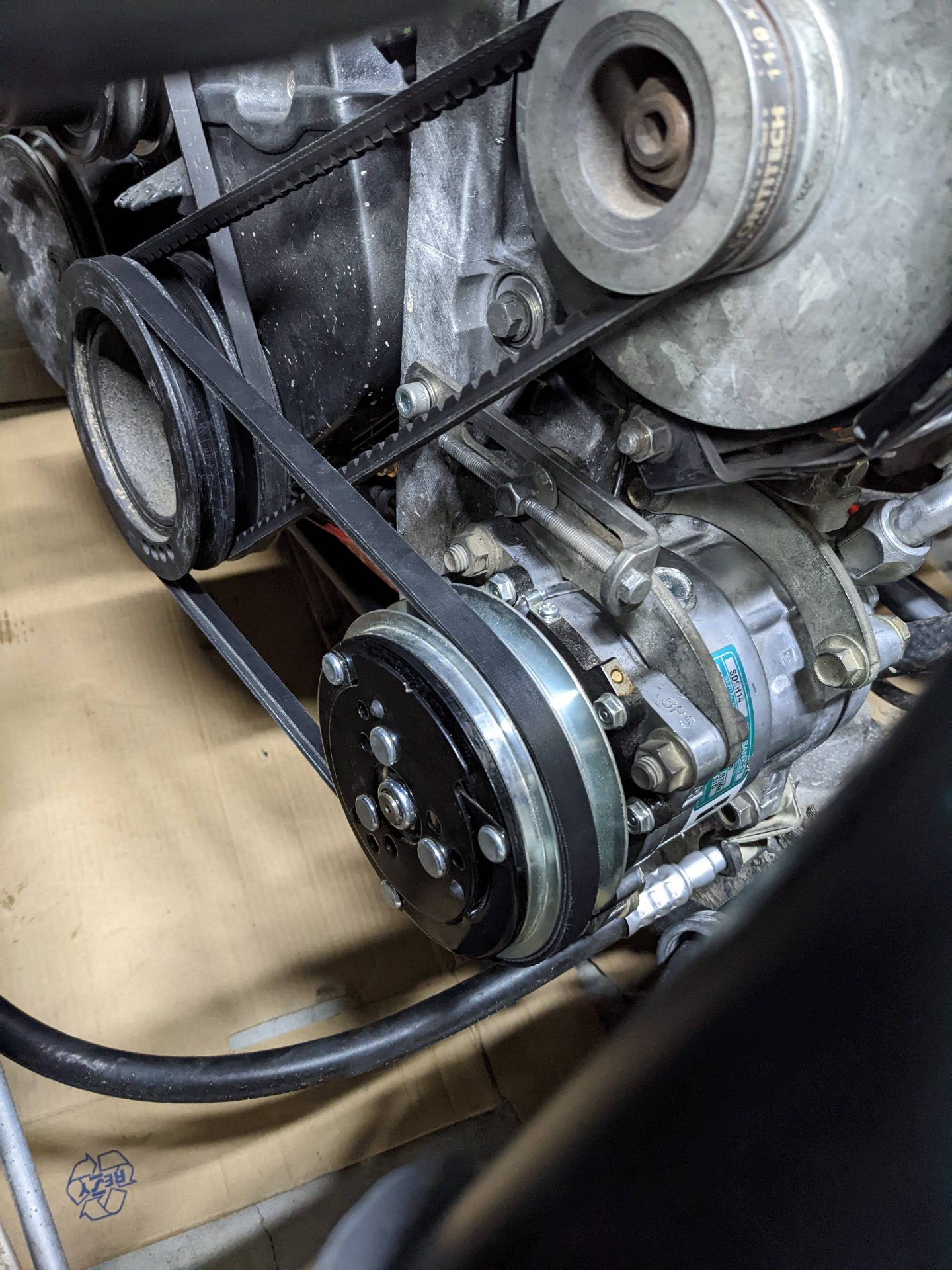
      Took a couple of goes to get the right Belt - there's differing figures out there but I'll say this:

      Original belt is 12.5 x 0975, which is an unusual width and seems to be mostly used on euro cars from what I could tellMost places (including gates) list Aircon belt as 13a0950, which is too short.13mm belts sit in the groove well in the engine pulley side, but sit proud of the top of the pulley on the compressor side. 

      If I can find a good 12.5 x 0975 I'll be happy as it should sit better in the compressor pulley I'd imagine.

      I didn't realise I had the wrong accumulator until I went to get everything installed. That set me back about a week and a half before they got one in stock and I could book in for another time. 

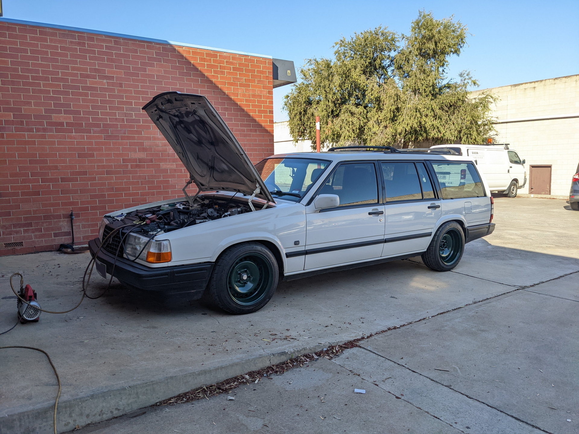
      Then when the time came, and they went to pressure test the system, they found that the compressor was leaking.. from the body of it, on one of the mounting ears! The guy there had a new one swapped in and pressure tested by the end of the day, but ran out of time to charge it, so swung by the next day and got it finished off. About 900g of r134a I think it ended up being, and it blows ice cold once cruising.

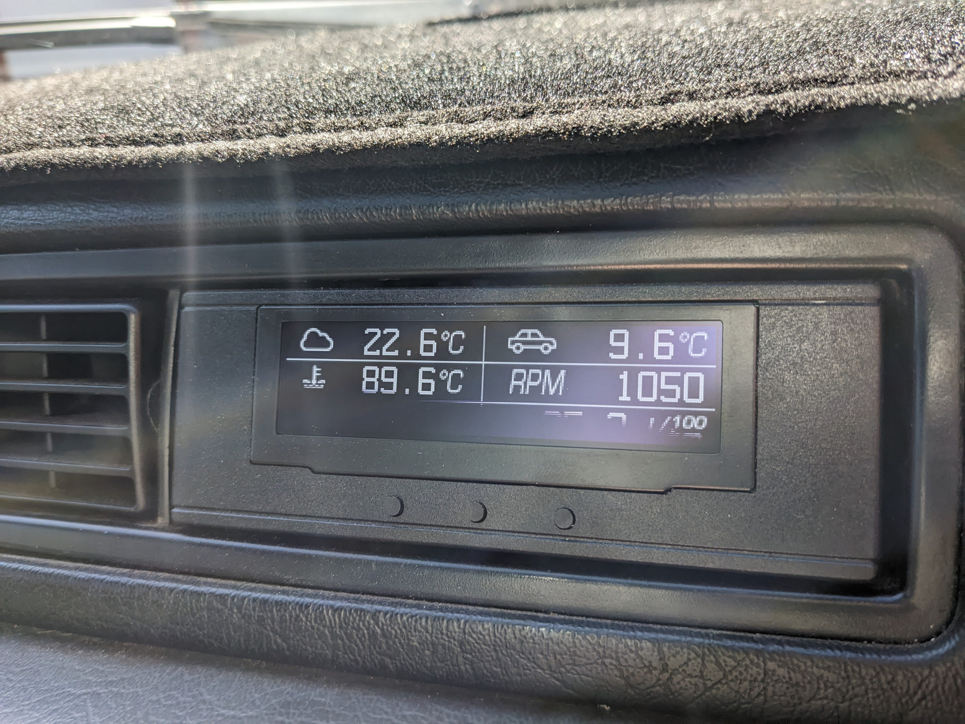
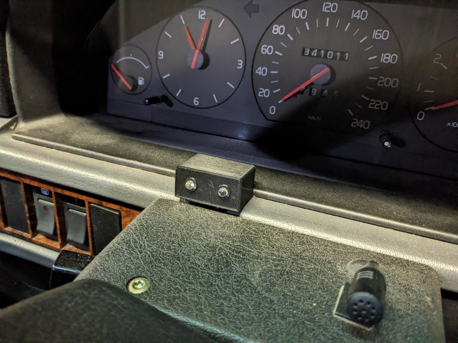
      Once you get cruising it tends to hover around 0C to 3C, even on a 35C day. Idling tends to be closer to 8-10c. Temp probe is directly behind the screen within the vent itself.

      With the aircon installed, and our next roadtrip a few weeks away, what better opportunity to test it out than on a 35C day that very weekend!

      Despite engine temps creeping up while in boost, going uphill with the aircon cranked (we're talking going up from normally around 87 on top rad hose to around 95c, it kept the cabin perfectly comfortable the entire time. I'm definitely going to be pulling out the intercooler and making some kind of shroud to direct air through the stack of Condensor and intercooler so all air actually makes it through to the radiator, as I think it's suffering a bit and cycling the rad fan more than it needs to.

      I've never had a project car with aircon, and even our 850 T-5 never had it working reliably so this is a real treat.

      Nice write up and pix.

      Great writeup. Hope you don't need to change the 2-port vacuum motor after having the dash apart.

      I like the way you've done the belts. Losing the alt belt or AC belt means you still have a water pump belt.

      Handy info about the Jayair accumulator too.

      Dunno if we're talking about the same thing @Major Ledfoot though I do still intend on getting one of @asiandriver's silicon replacement bellows if he's still got some, but that'll be another day. If the vacuum motor is a thing that goes as well, then.. well it's an old Volvo so I knew what I was in for. ? Getting the central parts of the dash off isn't much of a chore for me these days, as I've had it out enough that it's just a matter of just putting the time aside to do it :) I'm more worried about having to do heatercore and A/C evap on our 850..

      Pretty sure the belt configuration is standard 940 fare, and yeah I do agree it's a good setup - having some isolation from each accessory is nice. For the most recent roadtrip after all these changes I had just about every spare part packed into every nook and cranny that you could find, including an additional one of each accessory belt in case one let go. I'm not hugely used to V-belts so it was hard to gauge if I was over-tensioning them or not. I've had a alternator belt let go in our 940 in the middle of nowhere in the Czech Republic so I'd rather be prepared in case it happened again!

      Thank you once again for the kind words.

      Looking great and I'm enjoying your posts very much.

      Yes that belt arrangement is standard for a 940. It's some comfort having the accessories isolated from each like that.

      I run a 13mm belt on both of my 940s air con compressors. They had that size belt installed when I got them both so I just went with it but, yeah, I've noticed it rides a bit high on the compressor pulley.

      That pin on the control unit circuit board - is that the one under the little black relay? I've had to resolder that on both of my 940s. Seems it's a common problem. One of them has had the control unit replaced at some stage and I'll bet that was why.

      That pin on the control unit circuit board - is that the one under the little black relay? 

      Yes, that's the one - seems it's simply a fact of life for these control units. I'm glad to have some on standby in case of failure. If I had another fail, I might swap out the relay entirely with a new one to see if that makes any difference.

      These boards are aging and I can't remember where I read it but I think there's a decent amount of current going through that pin with the A/C on (4A springs to mind?) presumably to power the clutch on the compressor, so perhaps something to consider in the future is using that pin as a trigger for a separate, external relay so there isn't so much current being drawn through that PCB, if that's in fact part of the issue.

      Good to hear the 13mm belt is okay at least :)

      8 days later
      November 2022 - Heat shields

      I wanted to make up some heat shields, one for the brake master and one for the oil pressure sender and its wiring that both live close to the exhaust manifold, so I broke out the cardboard and made some up quickly with some sheet metal I had lying around.

      Then the one for the oil pressure sender:

      It didn't take long and I didn't bother painting them, but I might do so one day. Function over aesthetics when you're prepping a car for a roadtrip!

      November 2022 - Antenna Mast

      Since purchasing the car the antenna mast has always been at half... mast.. eyy!

      I purchased a replacement mast from Skandix with one of my orders a couple of years back and it was 14 EUR or thereabouts.

      I pulled the old one out, and there was no fixing it - in the bin it went!

      The new one took quite a bit of wrangling to get it to go into the motor. I pulled the entire thing apart, thinking it was busted or had a broken motor or possibly had some old gear in it, only to realise I wasn't quite understanding how it worked. The mystical black box attached to the antenna motor had 3 wires, one of which was 12v battery constant, one was ground and the third was 12v to control up/down on the antenna. When 12v is supplied, antenna go up. When power was removed, after a couple of seconds the antenna would go down again.

      https://youtube.com/shorts/FDyeQ3r4-hw

      Right now I cannot figure out why the dash switch or my head unit doesn't make the antenna go up, but realistically that's not the most important thing, as long as we still (kinda) have radio, and now the antenna fully retracts into the car! I will get the antenna switch sorted as it's pretty useful when you're outside of big cities and want some radio.

      Those power antennas can be a PITA to install and get working right. Took me hours to get the one on mum's 740 sedan working properly when I replaced it.

      I had a problem with my 940's antenna years ago where it would extend up fine but often would not retract after switching off the radio or using the switch (basically the opposite problem you have). If I fiddled with both for long enough eventually the antenna would retract. Turned out to be a problem with the circuit board in the little black box mounted beside the antenna. I can't recall what the problem was but I replaced it with a spare I had on the shelf and it's been fine ever since.

      • deNs replied to this.

        interesting - your 945 doesn't have the radio antenna built into the LH rear cargo glass window....

        My 93 945T has one, and IIRC my former 945 NA (which is for sale again on Gumtree by one of its new owners...) also had the cargo window aerial. They also use an RF amp signal booster.

        Both of the 945s have the provision for an antenna in that spot, but that location was used in the both the 745s I've owned.

        Nice work on the heat shields - they don't have to look pretty to work.

        • deNs replied to this.
          Brad

          Those power antennas can be a PITA to install and get working right. Took me hours to get the one on mum's 740 sedan working properly when I replaced it.

          I had a problem with my 940's antenna years ago where it would extend up fine but often would not retract after switching off the radio or using the switch (basically the opposite problem you have). If I fiddled with both for long enough eventually the antenna would retract. Turned out to be a problem with the circuit board in the little black box mounted beside the antenna. I can't recall what the problem was but I replaced it with a spare I had on the shelf and it's been fine ever since.

          Good to know - in my limited searching it seemed like that black box attached to the antenna motor wasn't really documented in terms of what was inside it or how it functioned, presumably as it would just be a 'replace if not working' kinda situation. Because I was able to essentially bench test it like in the video, I'm confident it's working as expected, but much like some of the other parts of the dash wiring, there's probably a missing link somewhere I haven't yet found.

          Major Ledfoot

          interesting - your 945 doesn't have the radio antenna built into the LH rear cargo glass window....

          My 93 945T has one, and IIRC my former 945 NA (which is for sale again on Gumtree by one of its new owners...) also had the cargo window aerial. They also use an RF amp signal booster.

          Both of the 945s have the provision for an antenna in that spot, but that location was used in the both the 745s I've owned.

          Nice work on the heat shields - they don't have to look pretty to work.

          Didn't realise they had them fitted to the glass so early - I'd prefer the glass antenna but now I've had tinting, I'm definitely not gonna change it from this. Perhaps it was an option to have the glass antenna or for the fancier models or a matter of what the factory had available that week.

          You can put the antenna on the windscreen glass, I did that for my DAB+ antenna. I still have this setup today, I never notice the antenna, it looks bright in the photo but that's just camera flash. I'm assuming there is a similar FM antenna on the market.

          jamesinc I added a digital radio

            jamesinc

            You can put the antenna on the windscreen glass, I did that for my DAB+ antenna. I still have this setup today, I never notice the antenna, it looks bright in the photo but that's just camera flash. I'm assuming there is a similar FM antenna on the market.

            https://ozvolvo.org/discussion/comment/35026#Comment_35026

            How good is reception?

            December 2022 - Final Roadtrip Prep

            There was a couple of things left I really wanted to fix before going on the trip, so I decided to tackle them before we left. 

            Coolant level warning light

            These are normally a warning light on the dash, however it requires your cluster to have the diode installed at the position that the lamp is going to be wired into. Not really wanting to pull the dash cluster out right now, I decided I'd grab a couple of LEDs, design print myself a basic housing for them and at the same time, cover up a hole in the dash from the previous owner.

            I made it to accomodate 2 LEDs in case I found another use for the other one. It's got a couple of 510 ohm resistors in-line to drop it down to the correct forward voltage from 12v in, then switched by the float switch in the coolant tank then to ground from there.

            I tested it out when I was swapping out the coolant as part of the pre-roadtrip maintenance (though the coolant looked perfect, and really probably wasn't necessary..). At least I got to test the light worked, so that gives me some confidence. It's absolutely a feature worth having so you don't pop a headgasket over something that could easily be fixed.

            Cup Holder

            It's a silly modern convenience but one that definitely comes in handy. I believe I saw someone on instagram fit one of these to a 940 in the same location literally a month or two after buying the car in 2018 so I cannot take the credit here. It's screwed to the panel and I have spares in case I want to remove it and have no holes, but I feel like it's a small sacrifice to have a cup holder.

            That said, it's not the best at actually *being* a cupholder except for perhaps takeaway coffee cups, which I suppose what we'll mainly use it for. It holds pringles cans well though!

            eyy.

            Starter motor relay

            This was done because after a hot day (37C+), I got home, parked the car, then a few mins later opened the garage to put it inside and tried cranking but got nothing. Turns out a few people on tbricks had similar issues in hot weather with the solenoid on the starter getting heat soaked and that's where the idea to put a starter relay in came from. Essentially it's using the old starter wire as a trigger, and then using the battery lead to the starter as the source for current, so there should be no more issues with a lack of current. I'm keeping spare relays in case it doesn't like being in the engine bay there.

            Jumping ahead, but I believe this saved my butt when I accidentally stalled at a set of lights on a hot day in heavy traffic and needed to quickly restart.

            Starter heat soak - whoa boy; been there done that.

            The low coolant level warning light is a great idea. It's standard on the 960s, but not usually hooked up on 940s. Did you use the factory type sensor in the coolant expansion tank? My 945T appears to have the float already in the expansion tank, but the sensor isn't fitted - however I did buy the sensor which is supposed to somehow attach to the underside of the plastic tank. Was this your experience?

            Also IIRC the NA and +t 940s used different expansion tanks from factory.

            • deNs replied to this.