Major Ledfoot

You're very brave for taking on the wiring harnesses in a 940. Far braver than me! Thankfully, they're somewhat better than a 740, but the OE layout still leaves a lot to be desired. Not so long ago, I separated the EZ-K section of a 740 engine harness from the remainder, and it was quite a chore. Where you ask, "What even is this wiring?" - lol, that was a familiar site during that exercise, as the 740 factory harness had connections just like that!

Sorting out the main +12V feeds and mounting the terminal block for them properly is something very worthwhile, and you've done that.

The Green Book Wiring Diagrams are very good, and they show an extraordinary amount of detail for circuit tracing and wiring. But it's worth noting Mother Volvo changed a large number of details along the way in the 940 series, including for example the rear door wiring colours for YM 1995 compared to, say, how it's done in YM 1991 vehicles. The Green Book USB I have shows different wiring books for 91, 92, 94, 95, and IIRC 96+ year models, and that's just for the 940s.

That said, your story of reassembling the jigsaw is excellent and I look forward to further chapters.

Thank you :) I did groan when I found out that the main body harness was integrated with the engine harness, as cars I'd rewired ECUs for previously (not many) all had separate ECU looms. That makes life so much easier when they're separate, but it's just a matter of sitting down with a greenbook, multimeter and notepad and figuring it out.

I can definitely imagine that separating out the engine harness would be time consuming, and not something I felt was necessary to do here since I was keeping the LH2.4/EZK for now. Thankfully the 1995 manual I got somewhere on the internets appeared to match all the colours for the wiring loom in my car, despite the small difference. I used a 1991 loom because it was the best condition and the most complete and despite the colour differences in the occasional position, the main plugs for the engine harness all go to the right places.

There were other things that needed to be re-routed like the EZK->LH2.4 load signal wire that made a big loop around the engine bay on the MAF wiring connector, that needed to be routed a different way as part of the re-wire, so that ended up just happening in the drivers footwell between the two boxes instead.

There's more that I've done that I haven't documented here, as there's times where I just got into the headspace of doing the wiring that I stopped taking pictures and just did what needed to be done :D

0 gauge! That's huge. I used 2AWG for my starter and even that is slightly larger than the OE wiring if memory serves. You planning on a 1000W subwoofer or something?

  • deNs replied to this.

    Nice work! I enjoy the small custom jobs like your plastic fuse and amp board...keeps the mind active without being overly daunting, and it's satisfying to see the finished product! :)

    jamesinc

    0 gauge! That's huge. I used 2AWG for my starter and even that is slightly larger than the OE wiring if memory serves. You planning on a 1000W subwoofer or something?

    Heh, it was simply because I had it left over in my pile-of-wiring stash, left over from my brother-in-law's Jeep from years back I think. The ground wiring from battery to engine block is 2GA and from battery to chassis is 4GA. I did have a ground harness but it was in pretty average condition. I decided to rewire that when I got the two KnuConceptz terminals that allow me to easily have things like a quick-connect thing for my NOCO battery charger. Honestly, the 0GA wire is kind of a pain to work with, to route and such.

    The amplifier and sub I'm planning to use are from my first car circa 2007 - a 4x50W Response Amp, and a 6-inch 'Invisabass' unpowered slimline sub. Not exactly earth-shattering, but it worked well with the 6" component Jaycar speakers back in the day, so running the front some cheapy coaxials up front and the sub in the back from the amp should make for a passable first effort. The sub and amp fit under the rear false floor even with the spare in there, so when I get time I'll do that after the car is done.

    03-12-2019 - Injector Seals

    Initially at least, I'll be using the original EV1 style injectors that are the '91 FT bosch (0 280 150 804) injectors which have a flowrate of 337cc/min from memory. Interestingly, the FK ones were a different injector (0 280 150 357) and had a flowrate of 300cc/min. It pays to check!

    This is what they look like after the pintle cap and the orings were all removed:

    After a little clean...

    Now to replace them with some nice german-made Volvo OEM o-rings!

    With all the correct spacers and caps and orings on, all that's left to do is lube them up and install them on the intake manifold!

    Didn't flow test or clean them, just seals and chuck them in, but as part of progressive upgrades I'll probably swap them for something better, more modern with a better spray pattern and obviously a higher flowrate. Will probably upgrade injectors before ECU, so I'm getting the bits needed to do a clean resistor pack bypass in preparation for it so I can run hi-z.

    04-12-2019 - Heater hoses

    Finding heater hoses for RHD 940s is surprisingly difficult. I've since found a source for the heater pipe from the back of the water pump going to the top port on the heater core. The one from the back of the head to the bottom port on the heater core wasn't possible to find, and normally is where the heater tap goes.

    That said, the two hacked up original hoses I have were from two separate cars and they had the heater tap installed on opposite hoses, in case you were wondering.

    I took some LHD hoses and DIY'd some RHD ones.

    I ultimately used an oil cooler hose (top right) and a LHD heater hose (top left) to make a head-to-bottom-heatercore-port hose.

    And the end result.

    A 5/8" brass hose joiner was then used to join the two, and I'm not going to use a heater tap here. I might if I have issues once I get the aircon in but I like not having that failure point. I was able to source the other heater hose from a UK mob I got some other hoses from at the same time. The one above goes from the head to the lower heatercore barb, and the one was able to source new is from the water pump hose to the upper heatercore barb.

    I've had to replace heater taps and hoses in the recent past on both my 940s.

    Instead of retaining the poorly designed factory system, where the coolant flow to the cabin heater core is merely interrupted when vacuum is applied to the heater tap, I've opted instead for using a VT Commodore type heater tap, which bypasses coolant flow to the heater core when vacuum is applied at the heater tap.

    Using a 4-port VT Commodore heater tap not only has the advantage of being cheaper, it also allows for coolant flow back to the engine; see picture.

    Instead of just cutting off the coolant flow to the heater core (and therefore all coolant flow back to the cylinder head) in the OE factory system, using a 4-port tap 'loops' the coolant flow so that not only is the heater core bypassed, but there is also coolant flow from the pump pipe back to the head fitting near the cold side of #4 when vacuum is applied.

    I discovered the shortcomings of the OE system when driving down from the Blue Mountains one very hot day with the A/C on, and I engaged the 'Recirculate' function to drop the cabin temp down quickly as I reached the start of the M4. After 5 minutes at highway cruising speed, the engine temp went into the red. WTF??

    Little did I know then that engaging the 'Recirculate' function on a Seven or Nine engages vacuum to the heater tap, which consequently cuts off coolant flow to the cabin heater core.... and thus interrupts the cooling circuit. By design, the cabin heater core in these cars is normally always in the engine coolant circuit; cabin temperature is controlled and regulated by flaps in the heater box, instead of coolant flow to the heater core. So it was no wonder my turbo car was approaching meltdown on this 45 deg C day, given the increased load of high ambient temp, the turbo getting even hotter than normal, and the a/c running at full tilt, plus the interruption to coolant flow.

    It's a particularly stupid piece of design by the factory when you think about it - at the very time most folks are going to want increased cooling capacity in the cabin, they're going to put the HVAC into 'recirculate' mode when it's scorching hot. So IMHO this is a mandatory modification if you have A/C and you want to preserve your engine in Australia's high average temperatures.

    That's awesome that a VT tap is of that design. Thanks for writing up that post! Was helpful for clarifying it in my head. I read through this thread on tbricks when I was looking up options and decided against it partly for simplicity and I just couldn't make my damn mind up about what I wanted to do. I should have seen if there were any locally delivered options as well.

    I still need some later-model parts to get my A/C hooked up, but like some other things that's been deferred until after the car is on the road. If/when I hook up a heater tap and get the A/C going, I'll definitely go down this route. I just wish there was a bit more space to work on it back there!

    30-12-2019 - Power steering lines

    After having a brainfart while ordering from Skandix and not realising their pressure hoses were LHD, I sent that back with the intercooler.

    I got a local hydraulic hose mob to remake the original hose, not because it leaked but because I couldn't source a RHD replacement and I wanted to ensure it definitely wouldn't leak again. They made a decision for me to make it a 2-piece hose with a JIC/AN fitting on the swivel connector. I didn't ask for it and I was a little annoyed it wasn't a single piece, but I can see why they did it - it meant they didn't need to maintain the orientation of the twists in the pipe, so no big deal.

    It will do the job. I think they said they pressure tested it above some crazy figure so it'll definitely do. For the return lines, skandix were out of stock of the suction line the first time I ordered which has a the moulded u-shape in it, so I got that later down the track, but as you can see in the picture above, the smaller return line to the reservoir has been replaced there also. New copper washers all around too.

    31-12-2019 - UTCOMP-Pro

    I've mentioned it in passing, but the unit above is called the UTCOMP-Pro. It's a device from a friendly bloke in Poland that comes with an associated small screen and acts like a multi-gauge. The screen unit connects to the box that is effectively the 'brains' of the system. I figured that instead of having lots of different gauges for different things, that it would be nice and neat to have it all in the one display. It will monitor the following:

    • Oil Pressure (via 150PSI sensor)
    • Manifold Pressure (via Bosch MAP sensor)
    • Coolant Temp (via NTP sensor in upper rad hose)
    • Wideband O2 Reading (via Spartan 2 w/ LSU 4.9)
    • Interior temperature (via DS20B18 probe)
    • Exterior (via weatherproof DS20B18 probe)
    • Injector duty (piggybacked off LH2.4)

    It also has a buzzer for high/low alerting, which was a big plus in my eyes. The Pro version has other things like the ability to trigger an output upon certain conditions. Because the LH2.4 triggers the e-fan at too high a temp, I'm using this device to trigger a small 5V relay to ground the low-speed side of the e-fan at a given point.

    If you're wondering why I'm using a relay to control a relay, it's because the fan relay works when grounded, and the output from the UTCOMP only does +5v output on the one output channel, so connecting a 5V relay and controlling ground via the NO position seems to do the job nicely. As a backup, the LH2.4 will still turn it on, at its higher threshold.

    I made a little case for the relay that controls the e-fan relay, because of course I did.

    It's a relay shield originally designed to sit on top of a Wemos D1 mini, an ESP8266 clone type thing. Basically, a tiny Arduino board with WiFi. I just needed the relay because it suited the specs and it's what I had on hand.

    I made an engine bay sub-loom that connects all the sensors to the unit to a plug at the firewall so it can be easily removed or worked on.

    The Bosch 3-Bar MAP sensors is in the middle, to the left is the coolant temp sensor, and the plug on the right goes to the oil pressure sensor. The connector down the bottom goes to the passenger side of the firewall with the other LH2.4 plugs.

    The UTCOMP side of wiring might be familiar to those who know PC hardware - the connectors are just molex 24-pin PSU connectors 😃 I found it slightly amusing.

    The PCB for the buttons needed to be wired to the main unit. I had some spare 4-core wire from another project so the above picture is just after soldering the wires to the board.The provided case for the display didn't secure the screen in place, so I measured and printed out some supports so the PCB for the buttons and the screen were both supported when everything was sandwiched together.

    The display connector is down the bottom-right of the PCB. Connects via an IDC ribbon cable.

    And here's the result:

    Showing time and inside/outside temperatures.

    As you can see, the unit sits pretty nicely in the center vent. I've designed and printed a hood for it so it'll hopefully be easy to read in any weather, but it's pretty bright. It's a 3.2" OLED screen so it's definitely better for readability than a LCD screen would be, which are a less-expensive option for the UTCOMP. Here's a quick video of its first startup:

    My sincere apologies for the vertical video. The unit itself is configured via a USB port via a Windows application, and is easy to use. It's also possible to hook up an android device via an OTG cable so you can have a secondary display via an android tablet or phone with the UTCOMP App.

    And we're now in the present year of 2020! Hooray, the year of infinite possibility, maybe some travelling, who knows? *ahem

    12-01-2020 - Airbox finished

    The airbox I picked up second-hand was pretty much complete, but had seen better days. The original clips and the plastic parts on the airbox that the clips attached to were long gone. I wasn't going to do what the previous owner did and use self-tapping screws to attach the top and bottom halves, so took an alternative approach I'd seen elsewhere.

    I used some door close hinges from AliExpress to replace the self-tapping screws and hold it all down securely.

    It seems to hold it pretty tight, so I'm confident in using it. As you can see in the photo above with the top off, before riveting it in, the rivets get supported by washers so it doesn't get pulled through the plastic. Unfortunately the spacing and location of the plastic means only one rivet is used per hinge and there's some overlap, but meh.

    After looking at the above photo much later I only noticed the bulge of the top cover, though it should still seal alright. Was never going to be perfect.

    The one thing to do now is plug up the MAF holes as my MAF doesn't appear to use the mounting holes that exist in the lid. At least, from memory it was for the maf? Perhaps there was a bracket between the MAF and the airbox, but I can't remember. Anyway, will seal them up with some rubber blanking plugs most likely.

    Edit: I think the reason I only used 4 rather than more of them was... I think I only bought 4? ?Oh well.

    Those hinges are a brilliant fix for the cold air box - certainly less expensive than what I did, which was order a replacement from GCP, since someone else had also used The Self Tapper Solution on my old one.

    This thread was a great read, plenty of detail and fantastic to see your electrical work, amongst other things.

    Keen for the next update!

    4 days later
    01-04-2020 - Pilot bushing

    The FK engine came with a different pilot bushing to what is used on the engines with auto boxes, so I needed to remove the pilot bushing and retaining clip (don't lose it!) in order to put it onto the other engine I'm going to use.

    Question is, I didn't have the faintest idea of how to get it off the engine. That's where the most hilarious suggestions from the internet actually paid off.

    First, get some bread. _Don't eat it_. Easy for me, I grabbed some stale baguette I cut the outside off of (bottom right). It was rock hard so I had to moisten it some as well. Mmm, moist bread.

    You need something that just barely fits in the centre section of the bushing, which you can hammer. In this case I found a random M10-ish bolt from my stash. 

    Lastly, a hammer. Great! My favourite tool.

    Shove that wet bread into the hole, and keep shoving, using the bolt to smack the bread in more and more.

    Eventually, amazingly, the pilot bushing will push itself out from behind with the bread and you'll have a bready engine, but a pilot bushing in hand! Magnificent. Thus ends our tutorial. I loved the internet that day.

    Don't forget to clean out the bread.

    Every time I put my car in neutral, it smells like burning toast. I wonder why? Hmm.... :)

    Was that pilot bushing you pushed out with the bread trick from an auto or manual? The auto ones I've seen look a lot different, and manual ones are a bearing, so just curious.

    Great work!

    • deNs replied to this.
      01-04-2020 - Gearbox install

      I'm skipping a couple of things, but we'll get back to the minor points in due course.

      When the shipment to myself from overseas came in with the gearboxes and engine, it was at that point I knew it was actually possible to complete this. It was at that point I went to various online retailers and the following occurred:

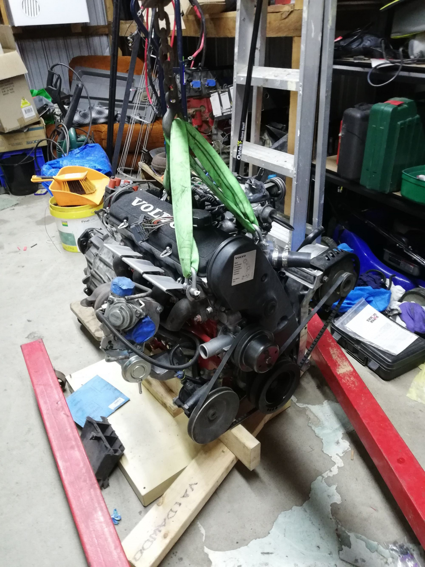
      So, what do we have here.. Nothing special, but it'll do the job:

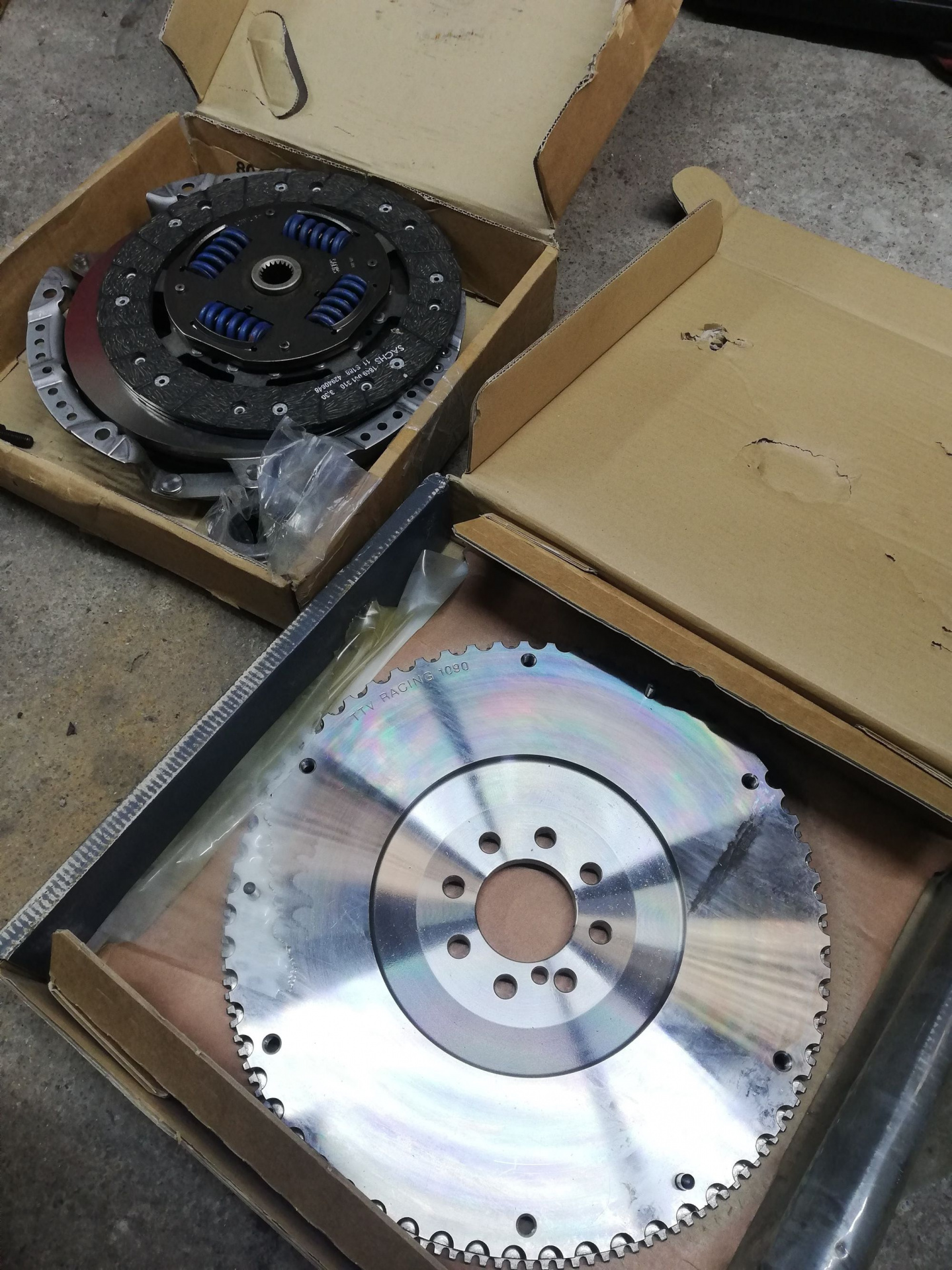
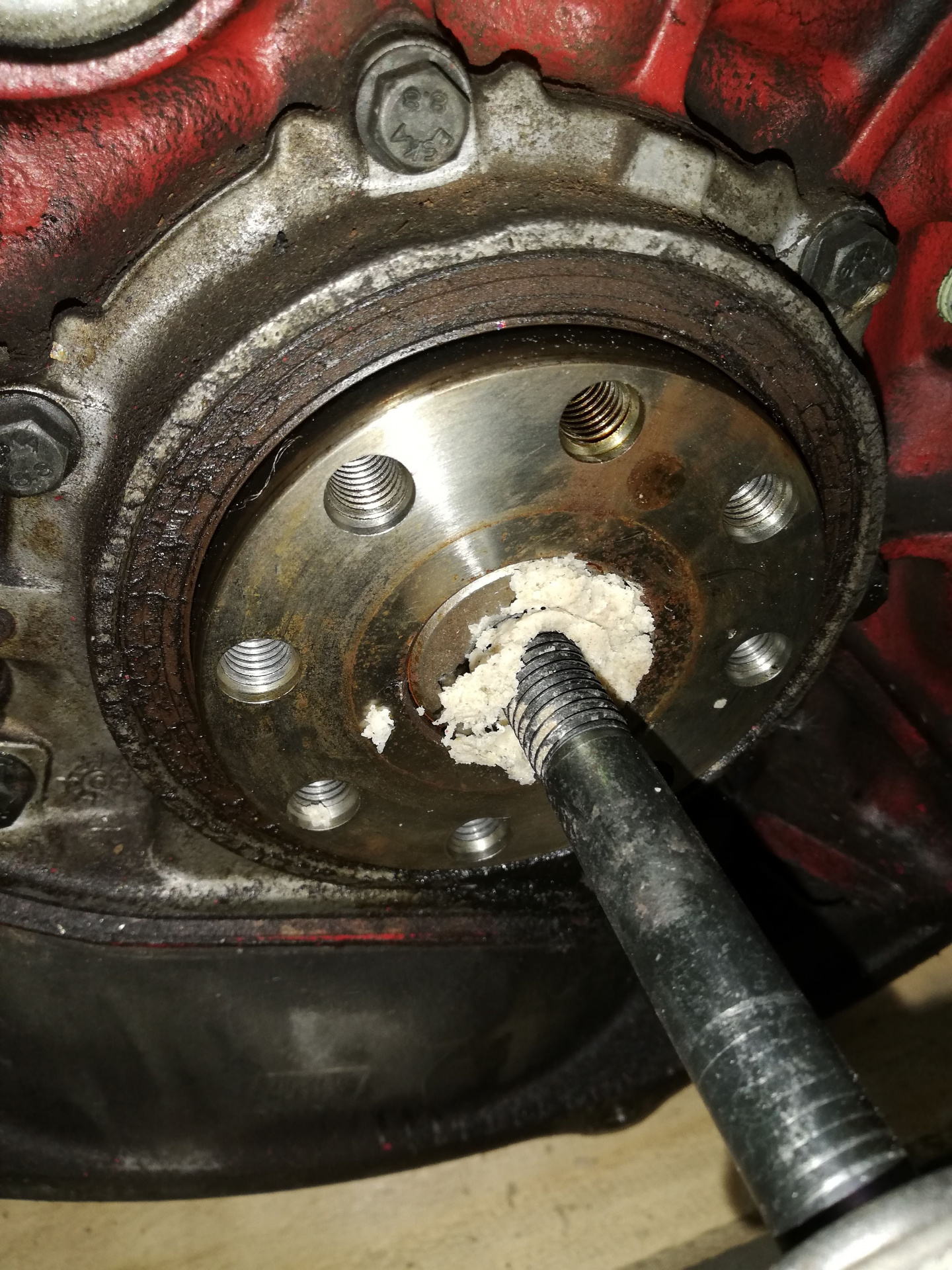
      After getting the engine off the crane, I've decided now's the time to install the pilot bushing, the flywheel and the clutch on the engine. It's finally time!

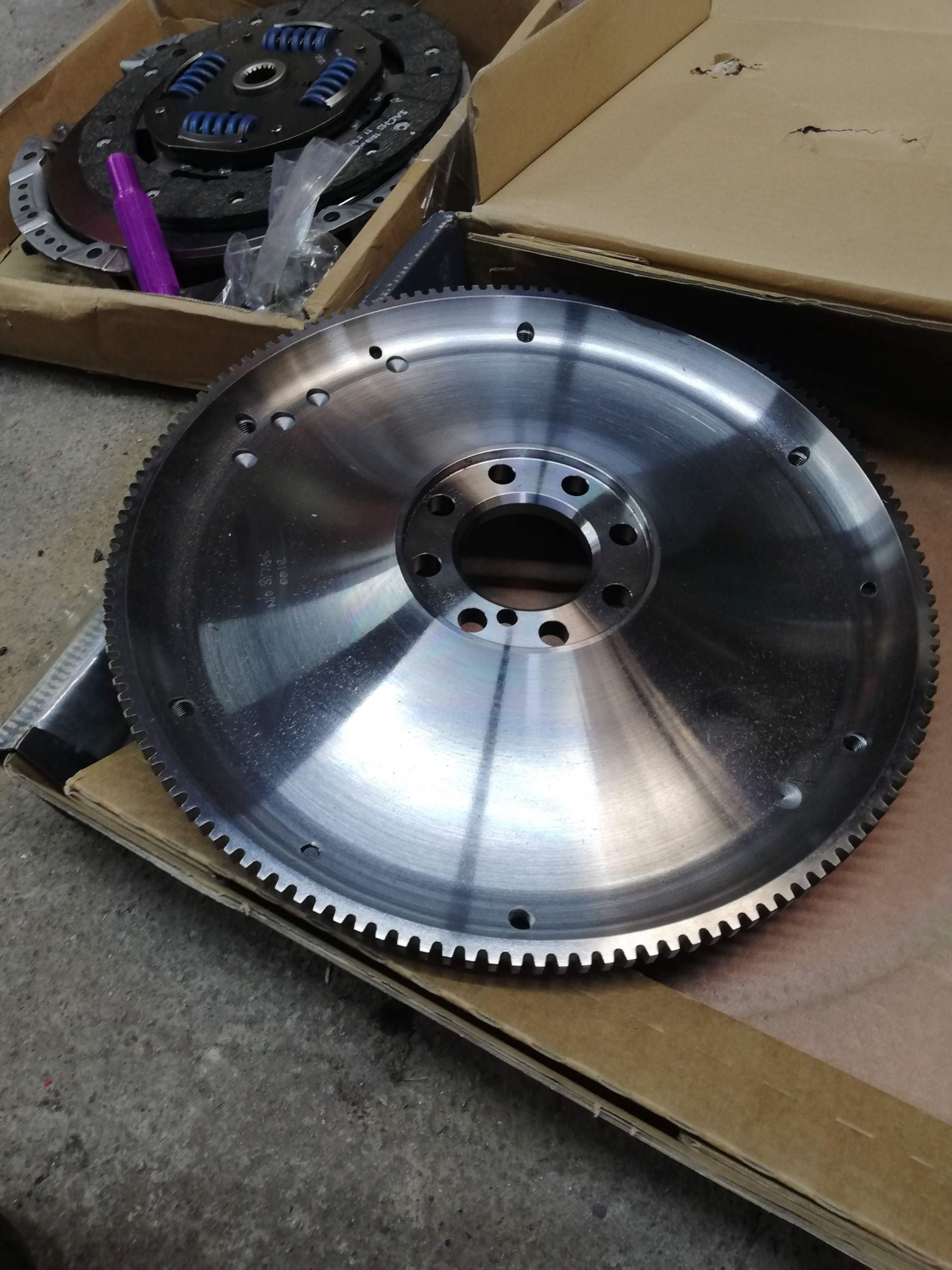
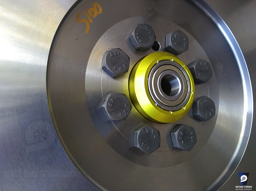
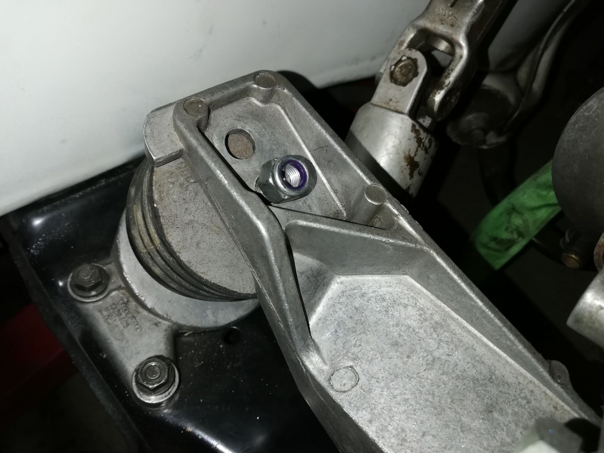
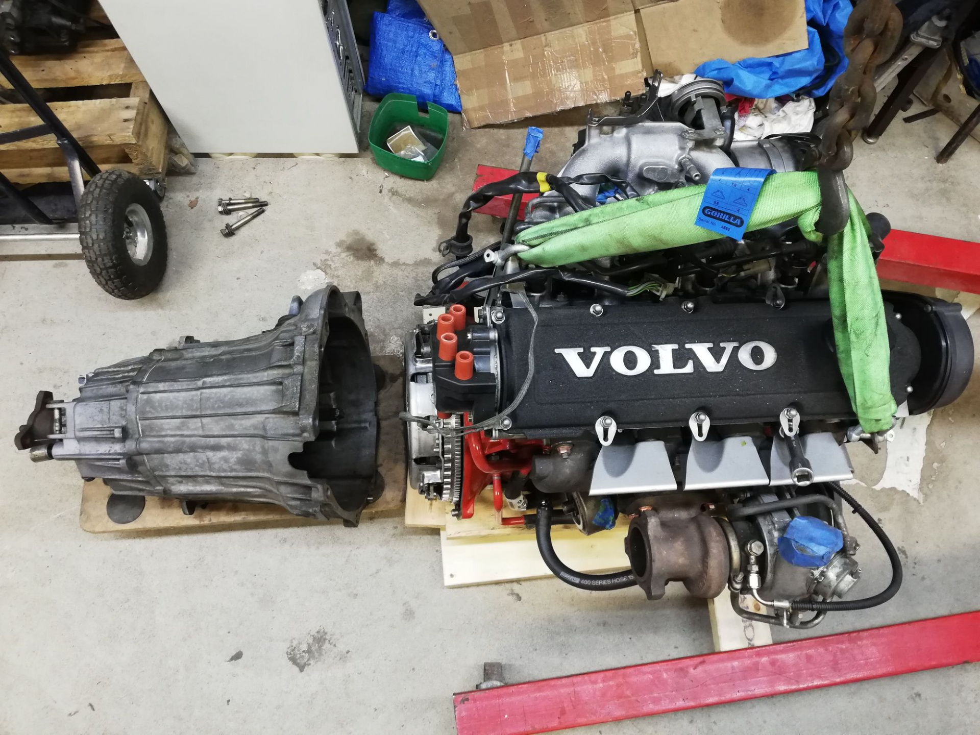
      TTV Lightweight flywheel and in the back, a Sachs 240MM clutch setup. The purple piece was a 3D-printed clutch centering tool from thingiverse.

      At 5.6KG, it's about half the weight of the original dual-mass flywheel that came off with the M90. Should spin a bit easier now!

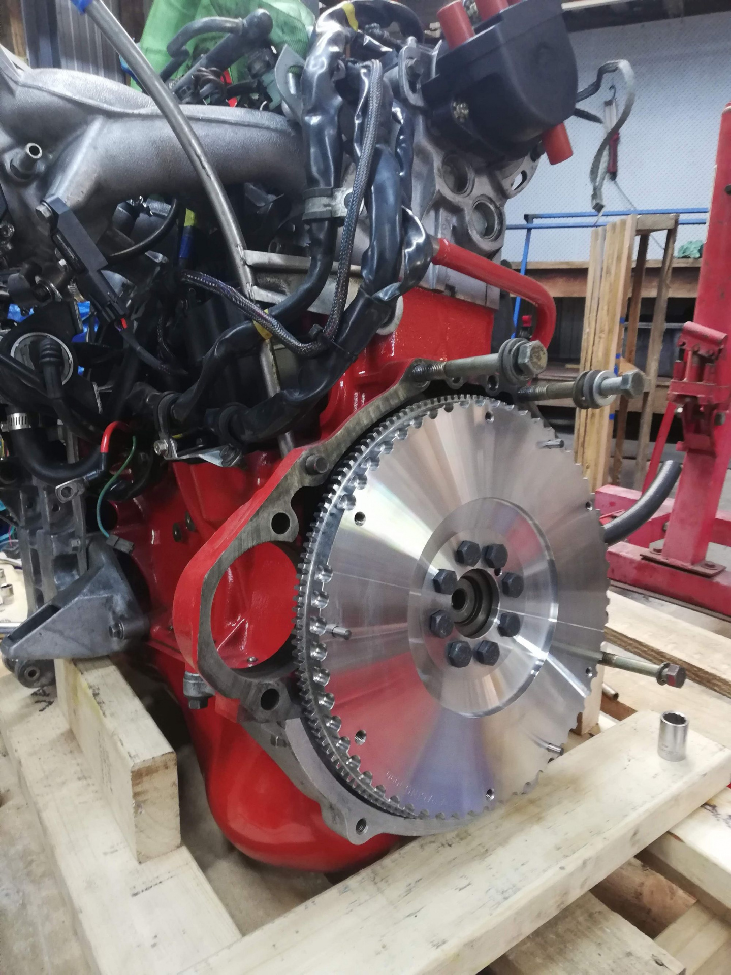
      Mmmm so fresh, new bolts and all.

      The Classicswede 'kit' came with flywheel bolts, a new pivot ball and all the bits needed to convert from a dual-mass flywheel to the LH2.4 single mass TTV flywheel.

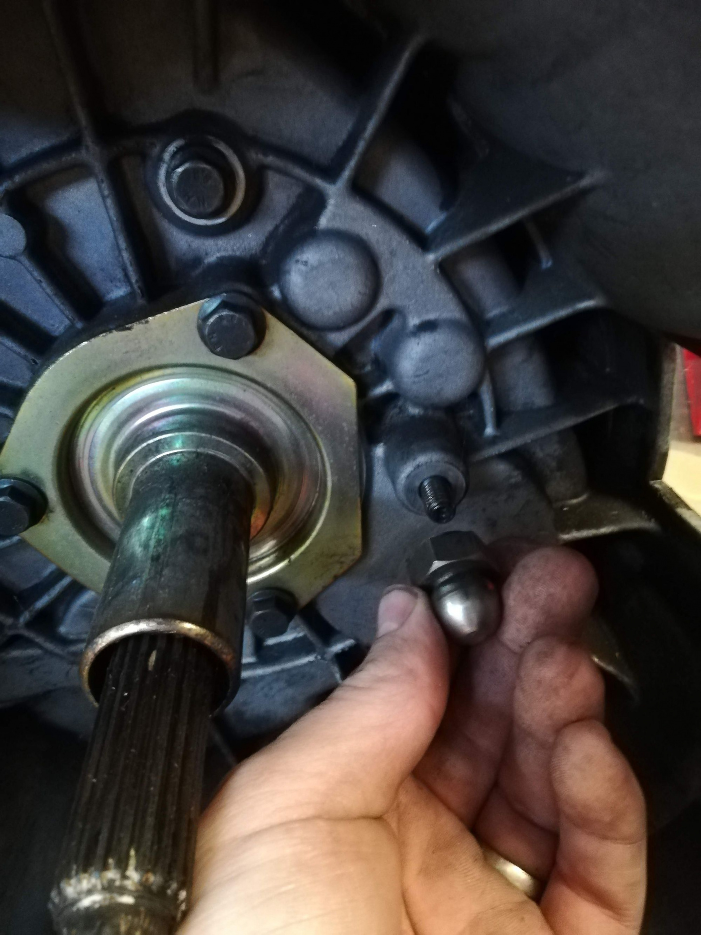
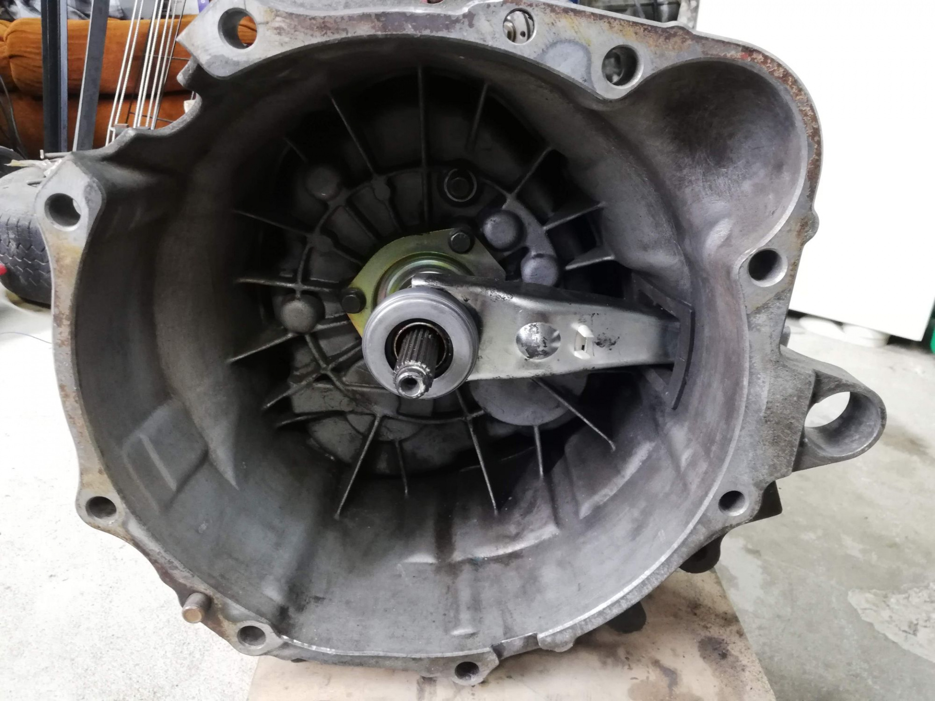
      Remove original pivot point from gearbox

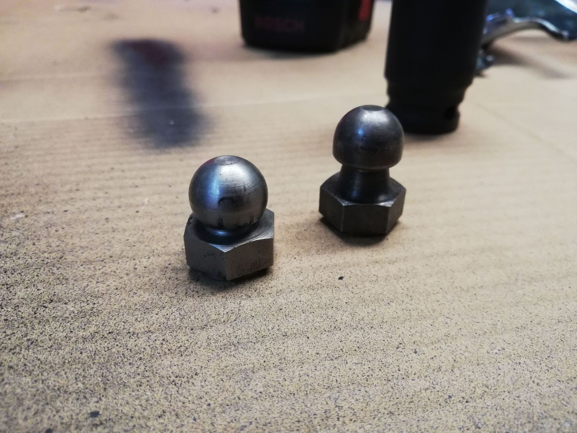
      Replace with extended pivot ball

      You can see the height difference in the pivot ball because of the different thickness of the flywheel.

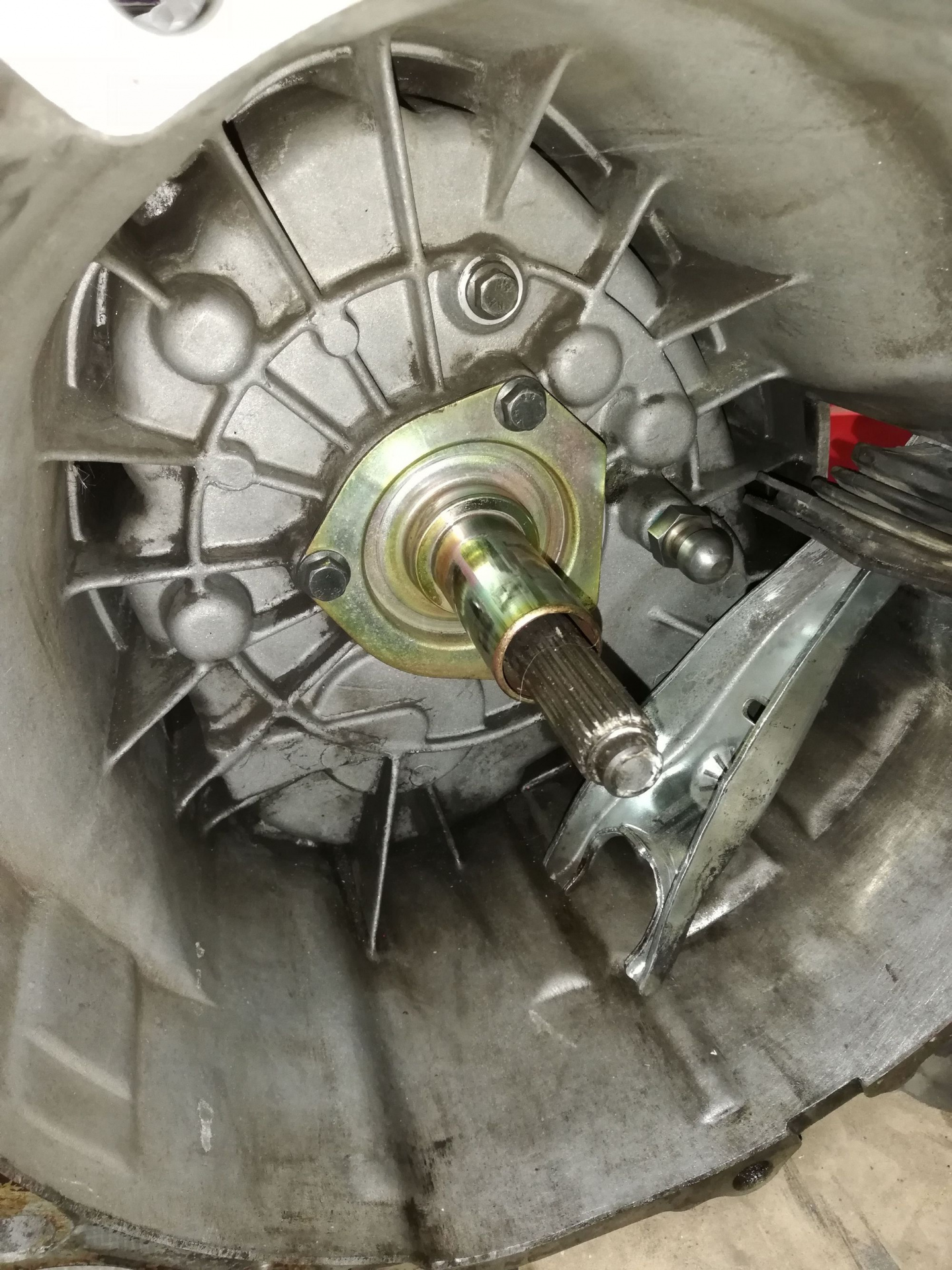
      Install clutch fork and throwout bearing

      Using an external slave and fork is old tech, but I'm not looking to figure out the complexities of a concentric slave here. If I lived in sweden I'd probably have a much more exciting build than this.

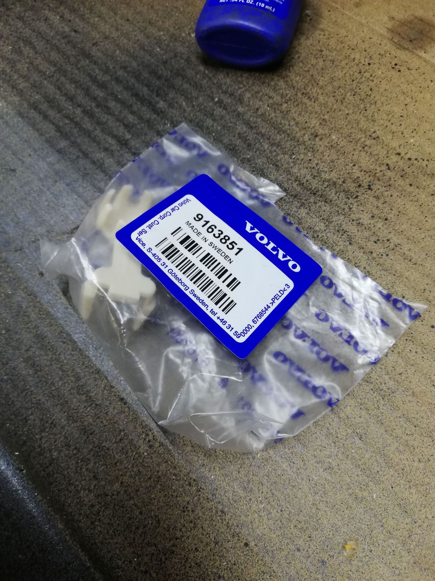
      New OEM pivot ball clip thingy for clutch fork - the first one of these didn't make it through the post intact but Dai sent a new one quickly which was nice.

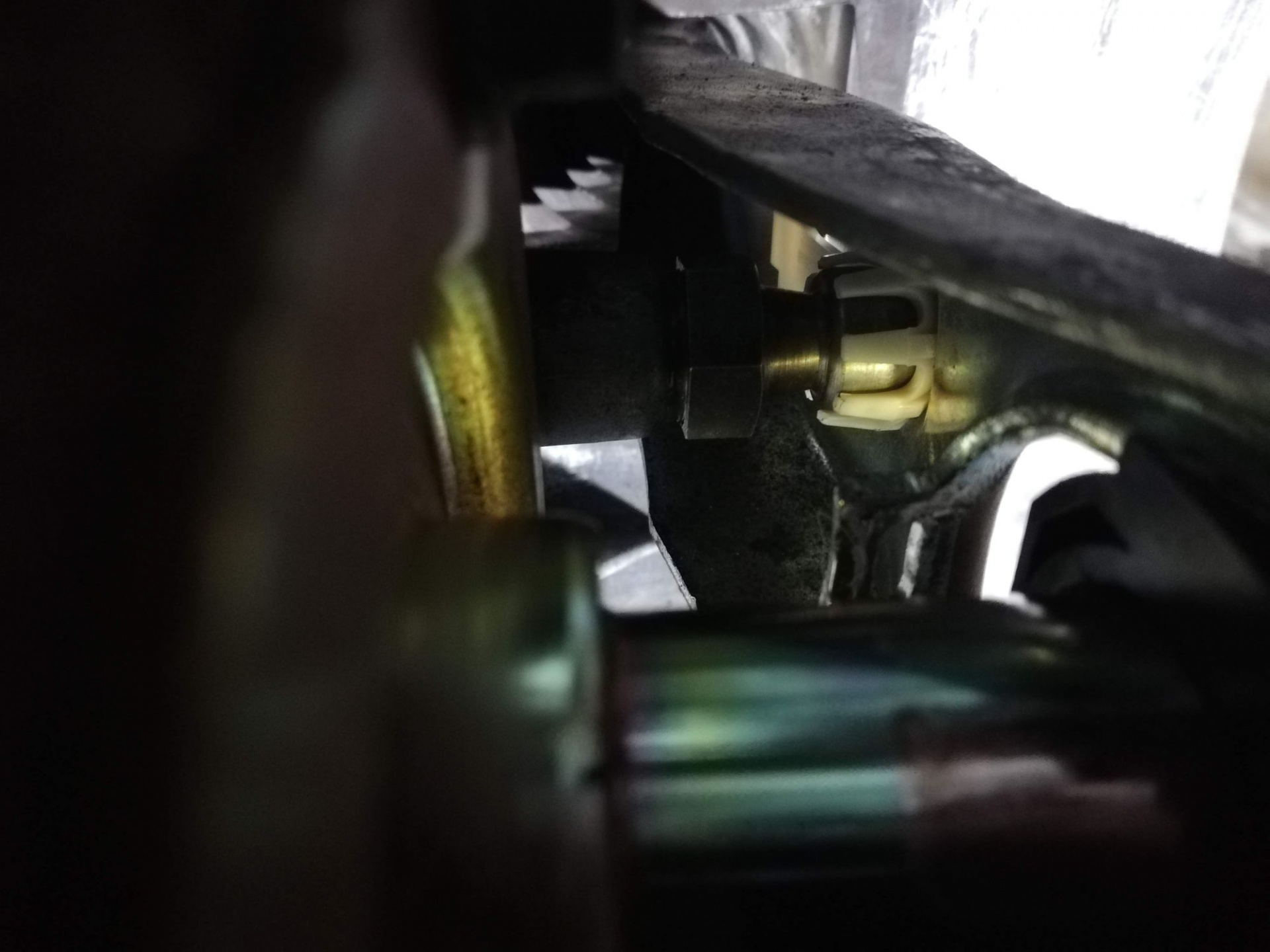
      Sneaky pic of the clutch pivot ball clip installed on the ball

      What it looks like installed after putting some graphite powder on the sliding part.

      Ready to be installed!

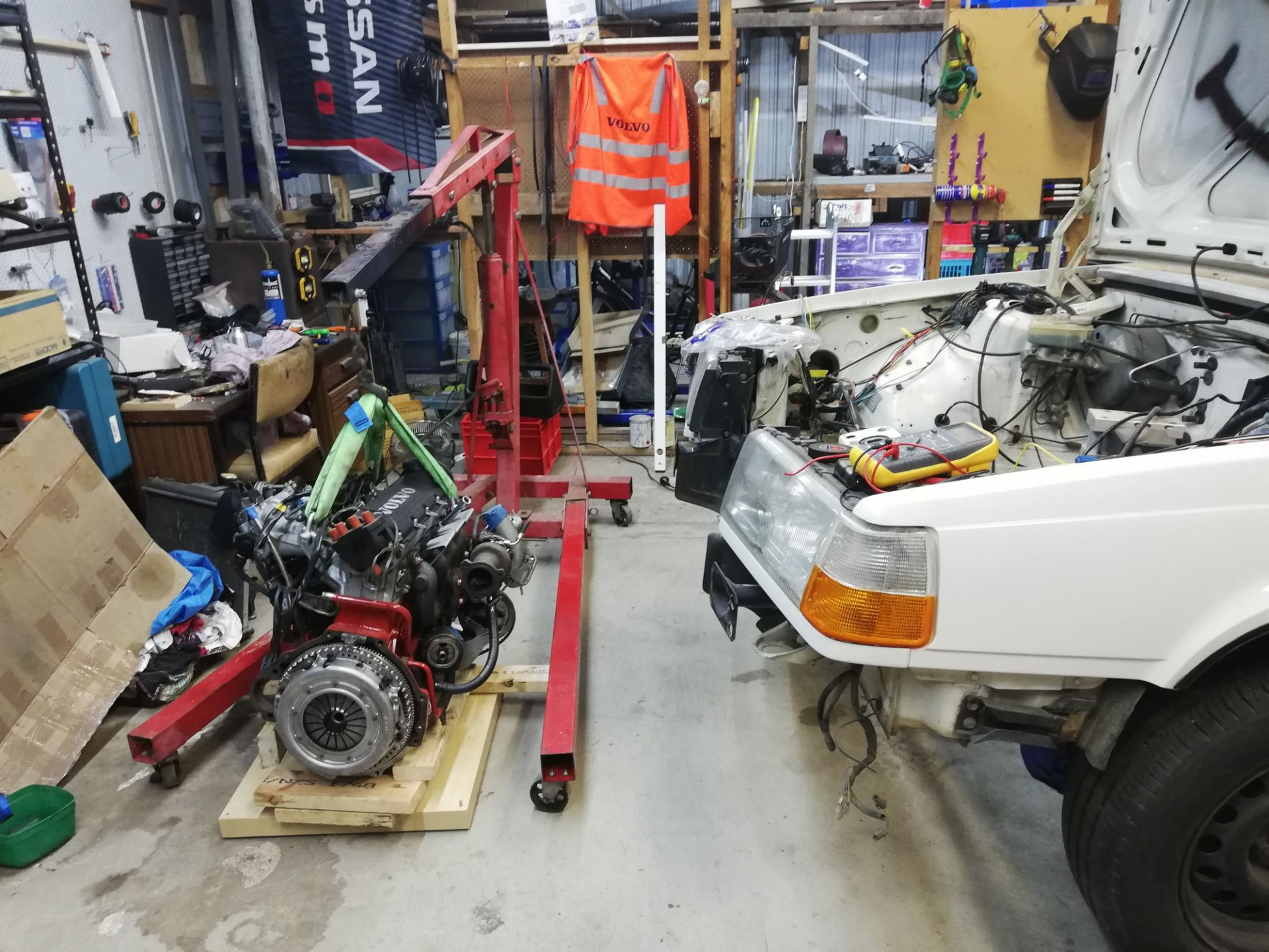
      Finally ready to offer up the box to the engine!

      "I'm ready for you now Brad. Isn't it obvi? I'm so ready."

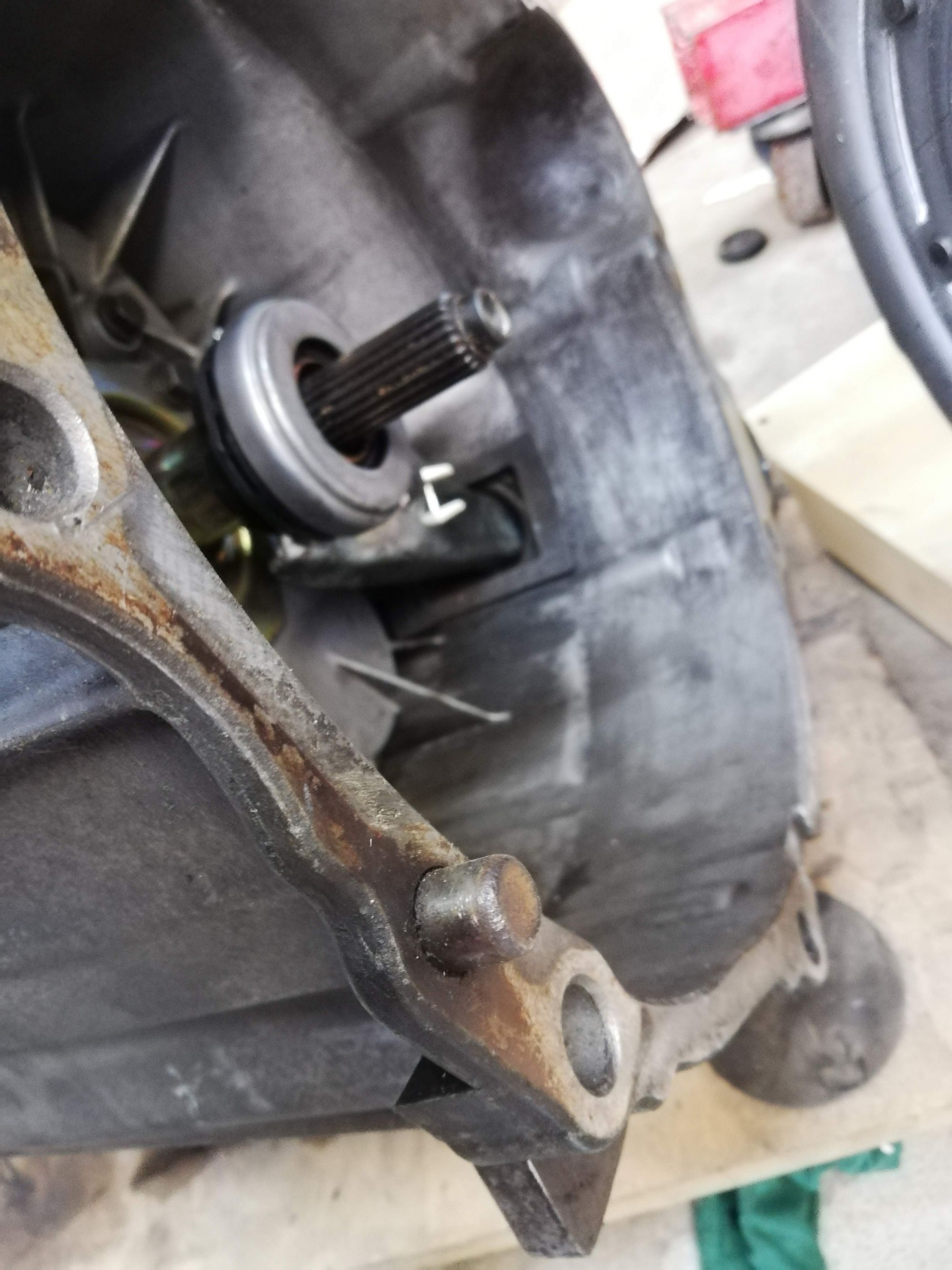
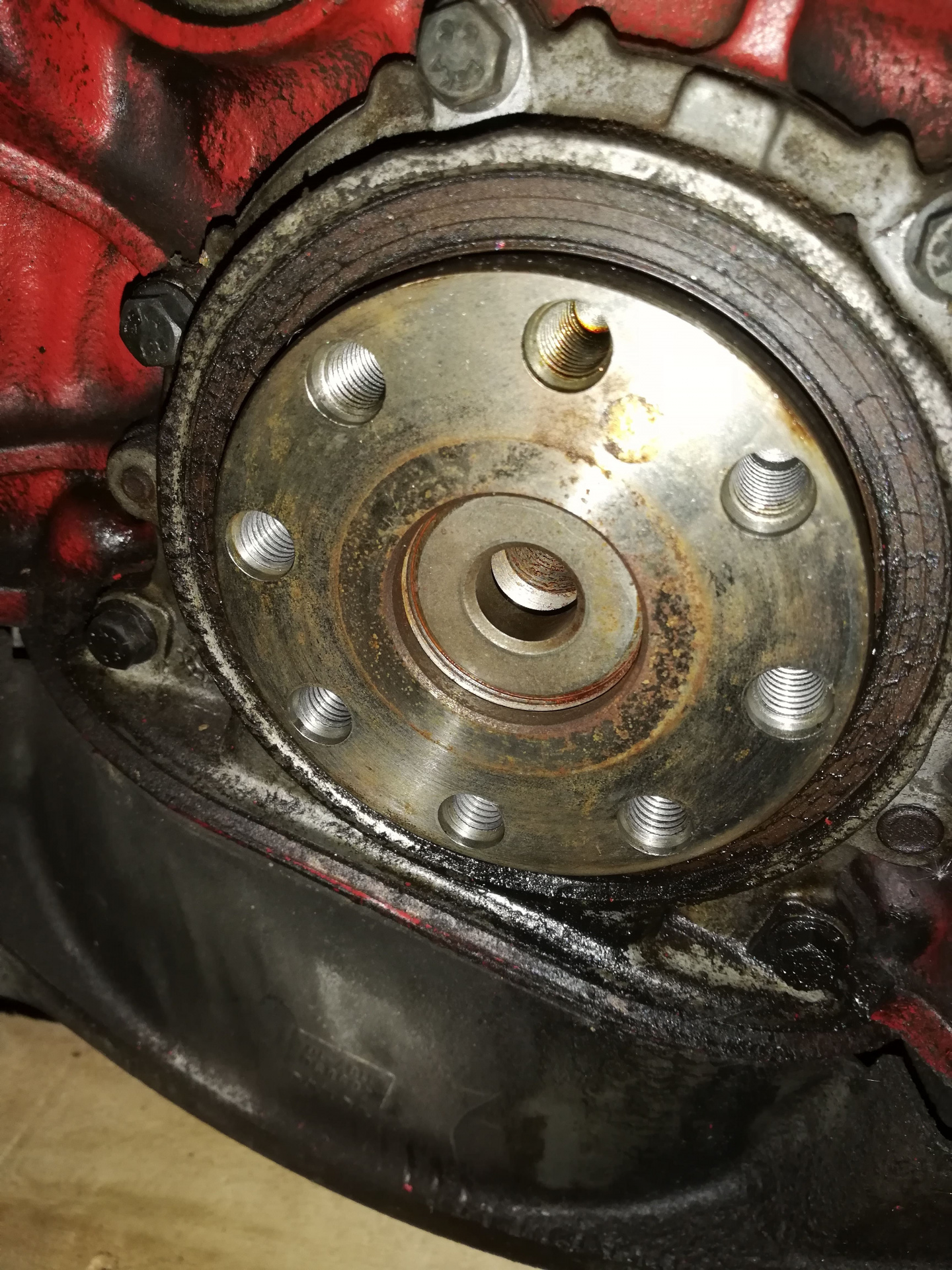
      But wait, I already have one of those dowels!

      But of course, the Automatic 1991 engine had a dowel that the M90 box already had. Hmm... what to do. Pull out the one from the engine or punch out the one from the gearbox... turns out punching the gearbox dowel was way easier.
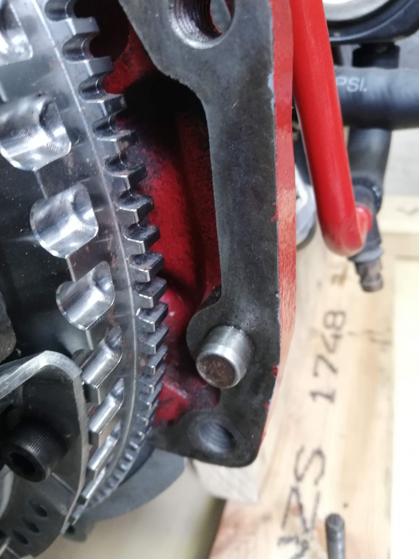
      "I was here first!"

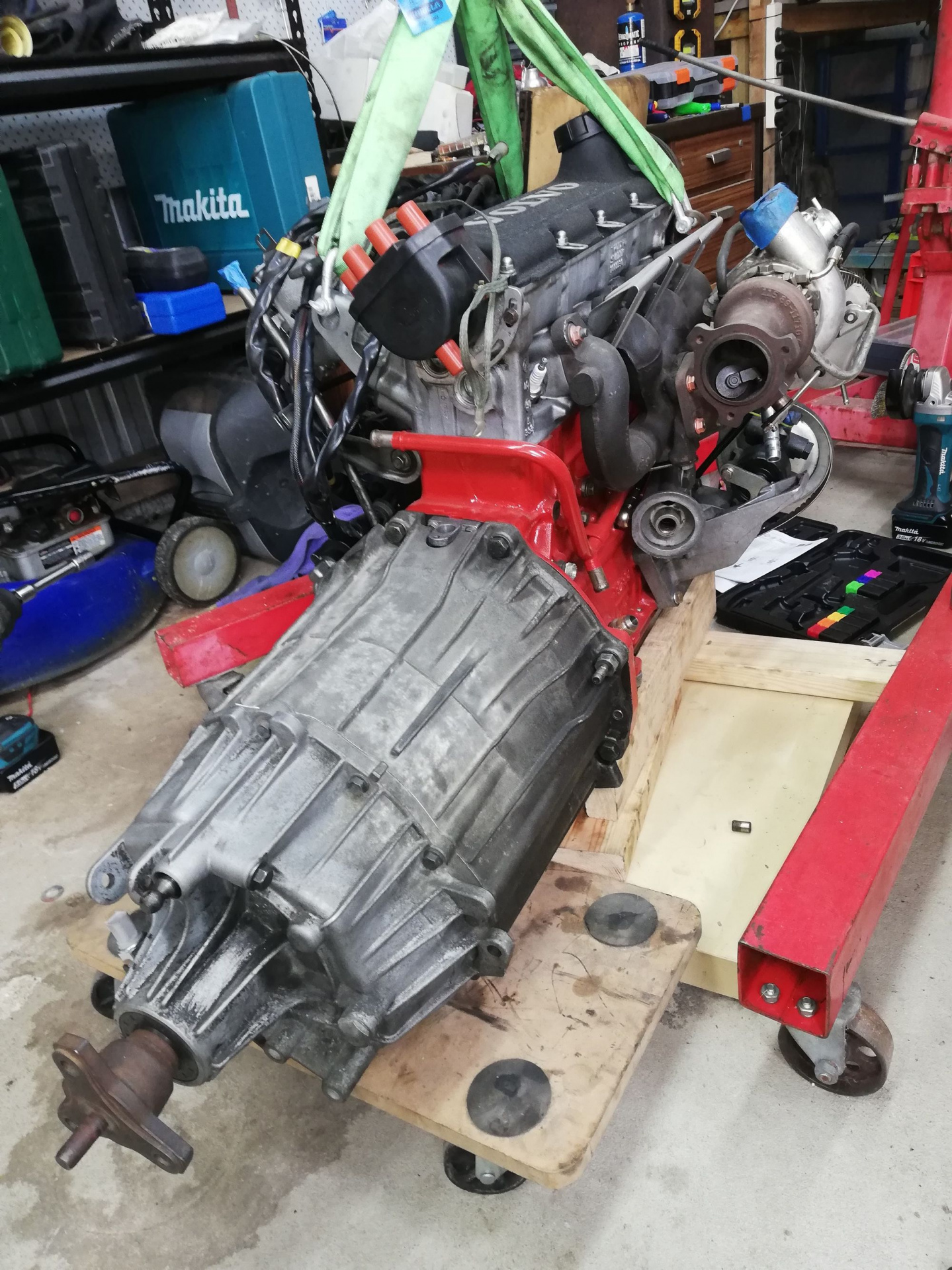
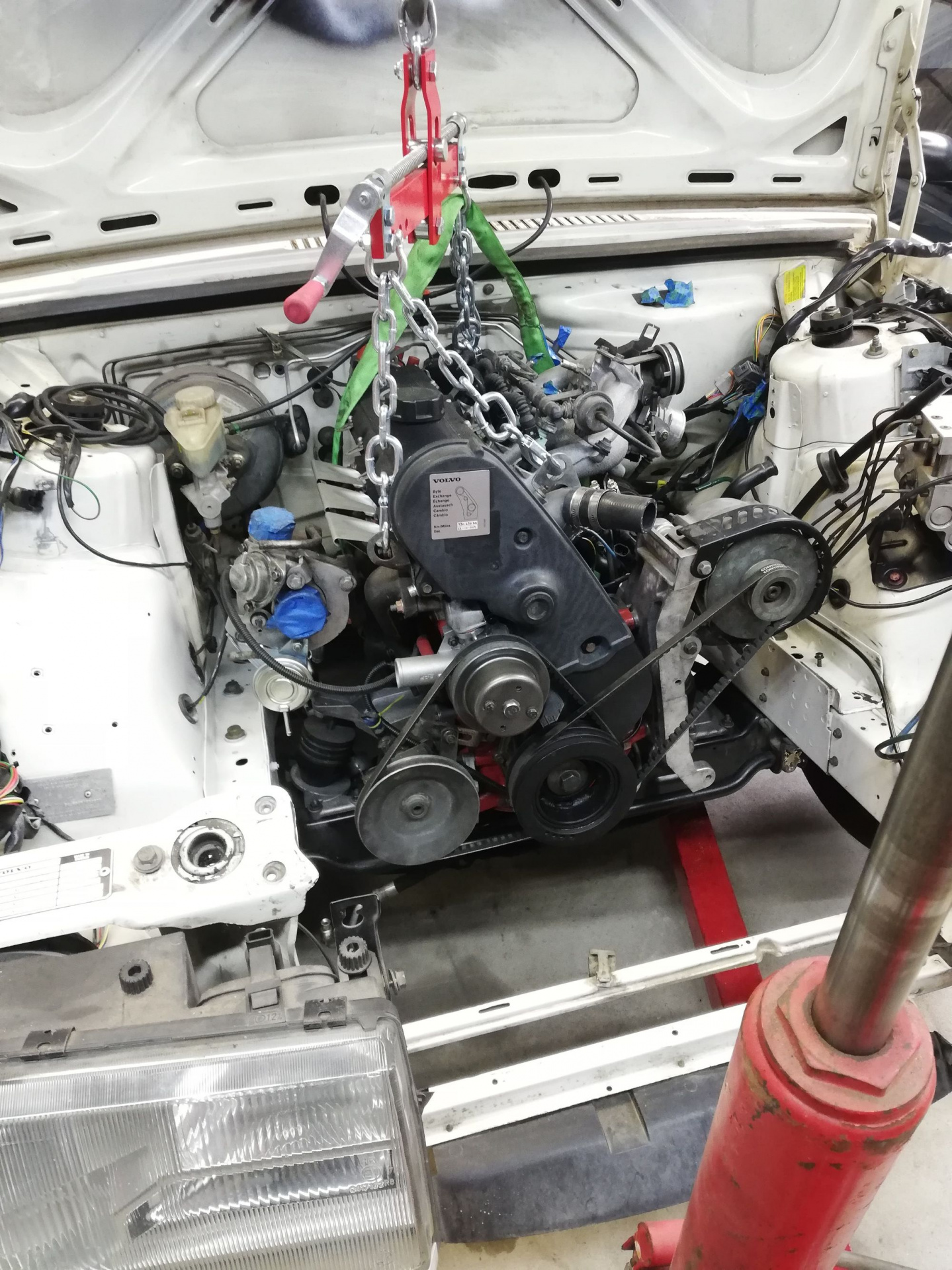
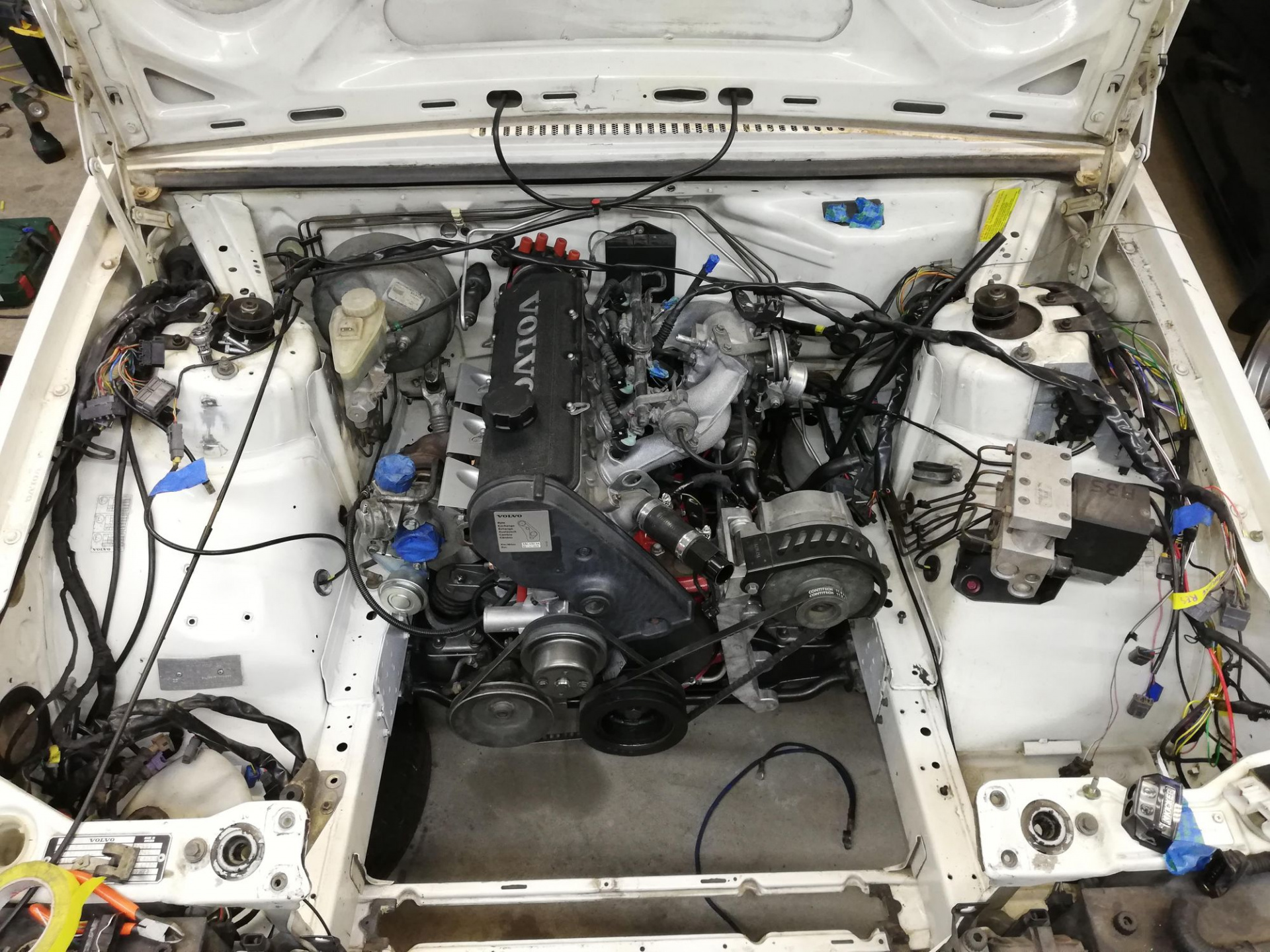
      And here it is, gently offered up to the engine! Pretty easy done with one person slowly with a dolly.

      Mmmmm so fresh

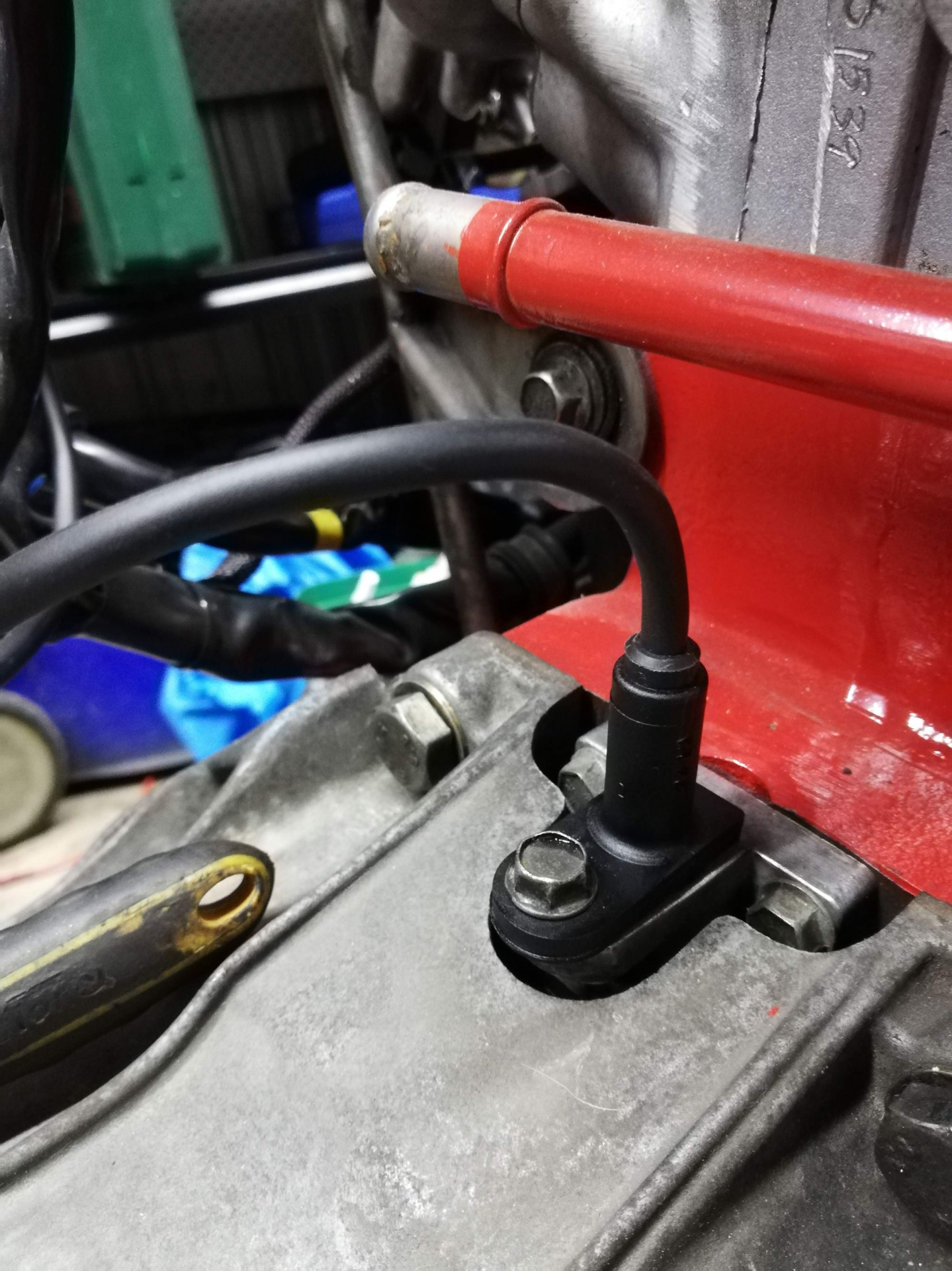
      Now we can install the crank position sensor!

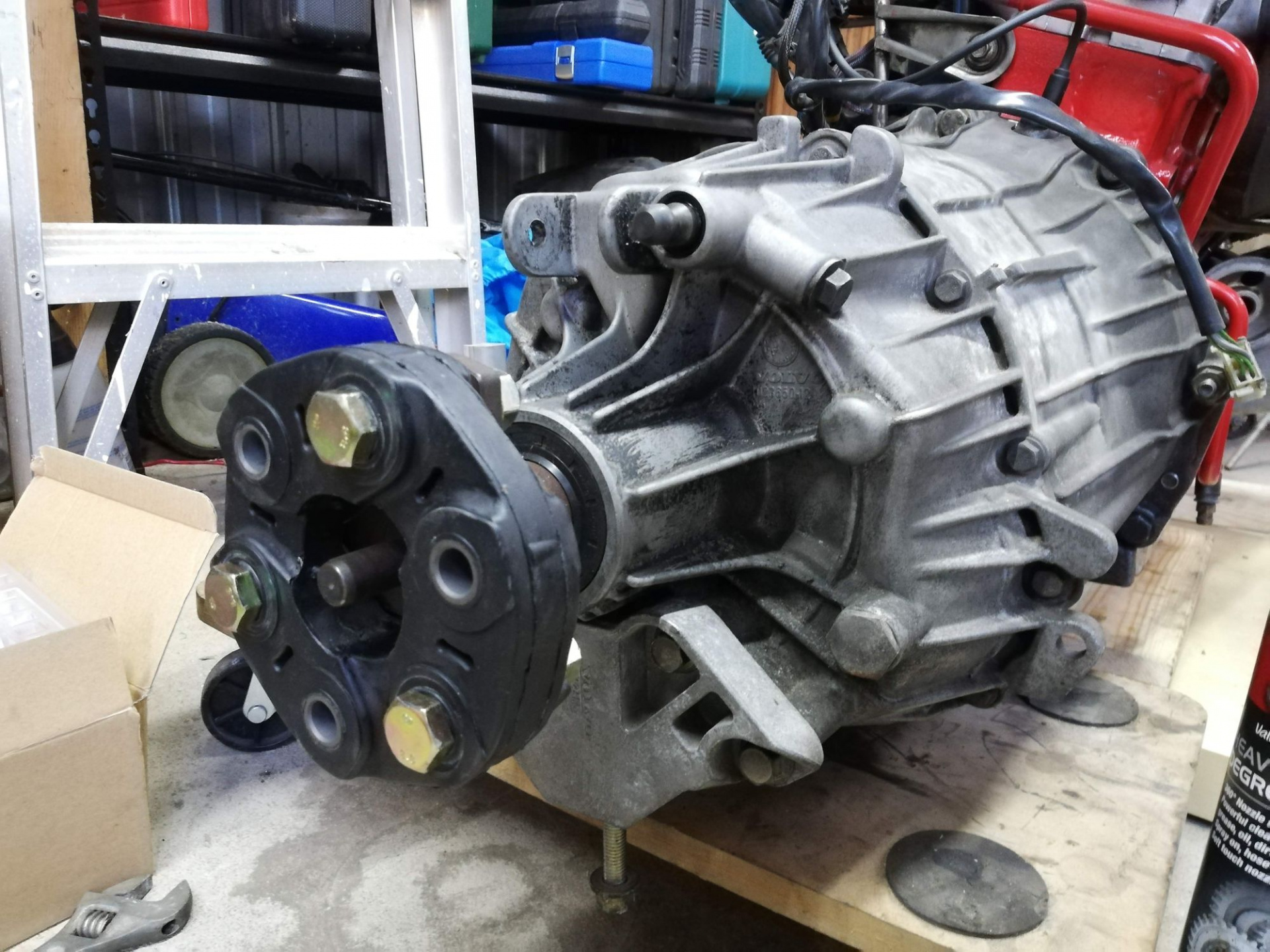
      Where did the name giubo come from anyway? Wikpedia had the answer, of course. I also found out I'd been spelling it incorrectly the whole time.

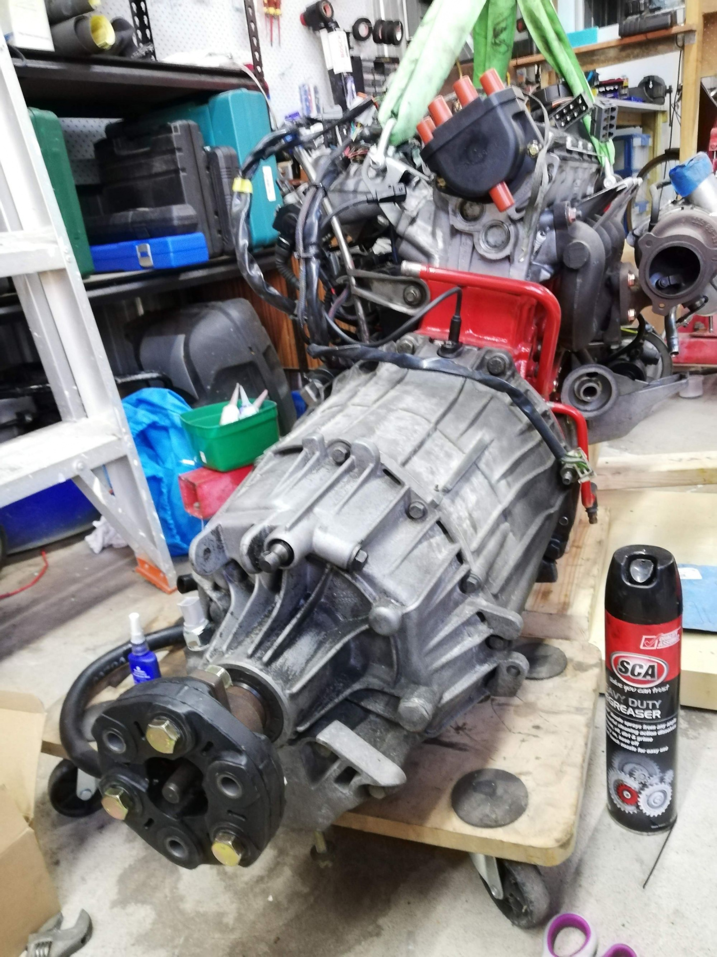
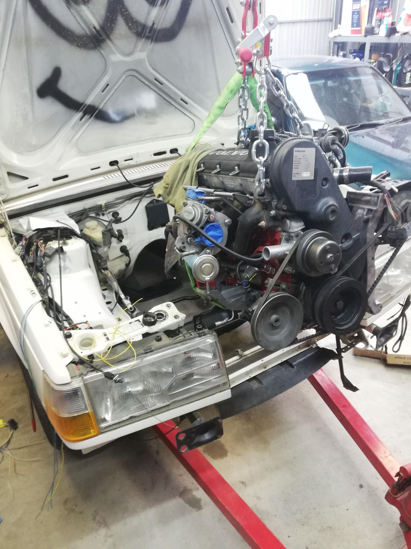
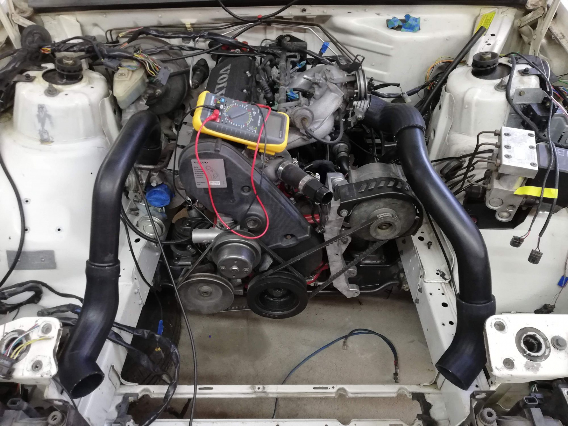
      Oh yeah... now it's ready.

      And now the giubo gets installed to hopefully protect the firewall a little from my clumsiness and we are ready to install the engine in the car!

      carnut222

      Every time I put my car in neutral, it smells like burning toast. I wonder why? Hmm.... :)

      Was that pilot bushing you pushed out with the bread trick from an auto or manual? The auto ones I've seen look a lot different, and manual ones are a bearing, so just curious.

      Great work!

      The pilot bushing in the pictures there is of the B230FK engine that had the M90 onto the back of it - was removing it so I could install it on the FT engine. The FT with the original AW70/71 had a thicker bushing in the back of the engine and had a countersunk face rather than a flat one like that. From memory the auto one was easy enough to remove by hand so didn't need to do it there.

      Before I installed it, I did a bit of reading about how the M90 doesn't actually have its input shaft supported by that bushing and some people make bearings that stick out that allow it to be supported like here. I've left it as-is and feel confident enough that it should be fine for how the box was intended to be set up.

      14 days later
      14-04-2020 - Engine Install

      Now we have the gearbox installed on the engine, we are ready to install it in the car! However, thanks to the COVID-19 pandemic, I've been in isolation for about 6 weeks by this point so I had to think of how I would do this safely on my own. I took a day off in lieu from work and got an engine leveller to help me do the job.

      Ready to accept the new hotness

      I wanted to get all of the engine bits sorted before it went in but I decided with the water/oil cooler that I wanted to get a new unit from Skandix when I do my next order. I didn't want to wait for then before installing the engine as I could do it, although slightly more difficult to do, while under the car.

      That way I could install the engine, see if there's any more parts I'm missing before I do another order with them. Shipping is expensive yo.

      So excited. With the engine leveller the job was way easier to do in order to angle it in so I didn't smoosh anything.

      Almost there!

      She's in! ....sorta.

      Here's a quick timelapse video of the engine going in:

      https://www.youtube.com/watch?v=wg3b5e_2_I0

      Though it was in lockdown, the dude in highvis was our plumber and finishing off some work. Wasn't sure how I'd go getting it in on my own as I've always done it with at least two people. Just takes patience and time I guess.

      Had some initial issues getting it in the hole. First time, I promise.

      I didn't realise which hole the engine mount was supposed to go onto on the drivers side. Took me some thinking overnight before I realised I had it in the wrong hole. I'm glad I didn't send the email to YoshiFab asking why the engine mount didn't look right! Hah..

      WRONG

      Right.

      Once in I had a quick look at how the intercooler piping would look laid out and got me excited and motivated to get it running.

      The excitement is building! Now to finish the wiring and keep doing all the fiddly little jobs.

      Looking good. Now I see why I had so much grief when I installed the engine on my 240...chains too short and the engine leveler I used was too long. I think I have a shorter/better one like the one in your pics that I'll use next time!