03-11-2019 - Wiring
The wiring in the dash and engine bay was not in a good state. Being the kinda person I am, I just couldn't do a half-assed job with this. On the bright side it meant I'm. now infinitely more familiar with the wiring on the car and have a lot more confidence in the state of the wiring. From memory the list as things unfolded included:f
Complete rewire the ABS loom (chopped/missing)Rewire all hacked out stereo wiring and put ISO plugs in its placeWire in UTCOMP multifunction gauge display and trip computerFind new way to do all heavy-gauge wiring including ignition and power distribution blocksRelocate Washer bottle wiring and washer level wiring to drivers sideRewire MAF wiring from passenger side (N/A) to drivers side (turbo)Wire in fuse boxes for all additional accessories and make suitable mount in glove box
That said, there was so many more things that needed to be cleaned up. This was just off the top of my head. The Volvo greenbook with wiring diagrams and whatnot was infinitely valuable here.
First up, the headunit wires were in need of some attention:
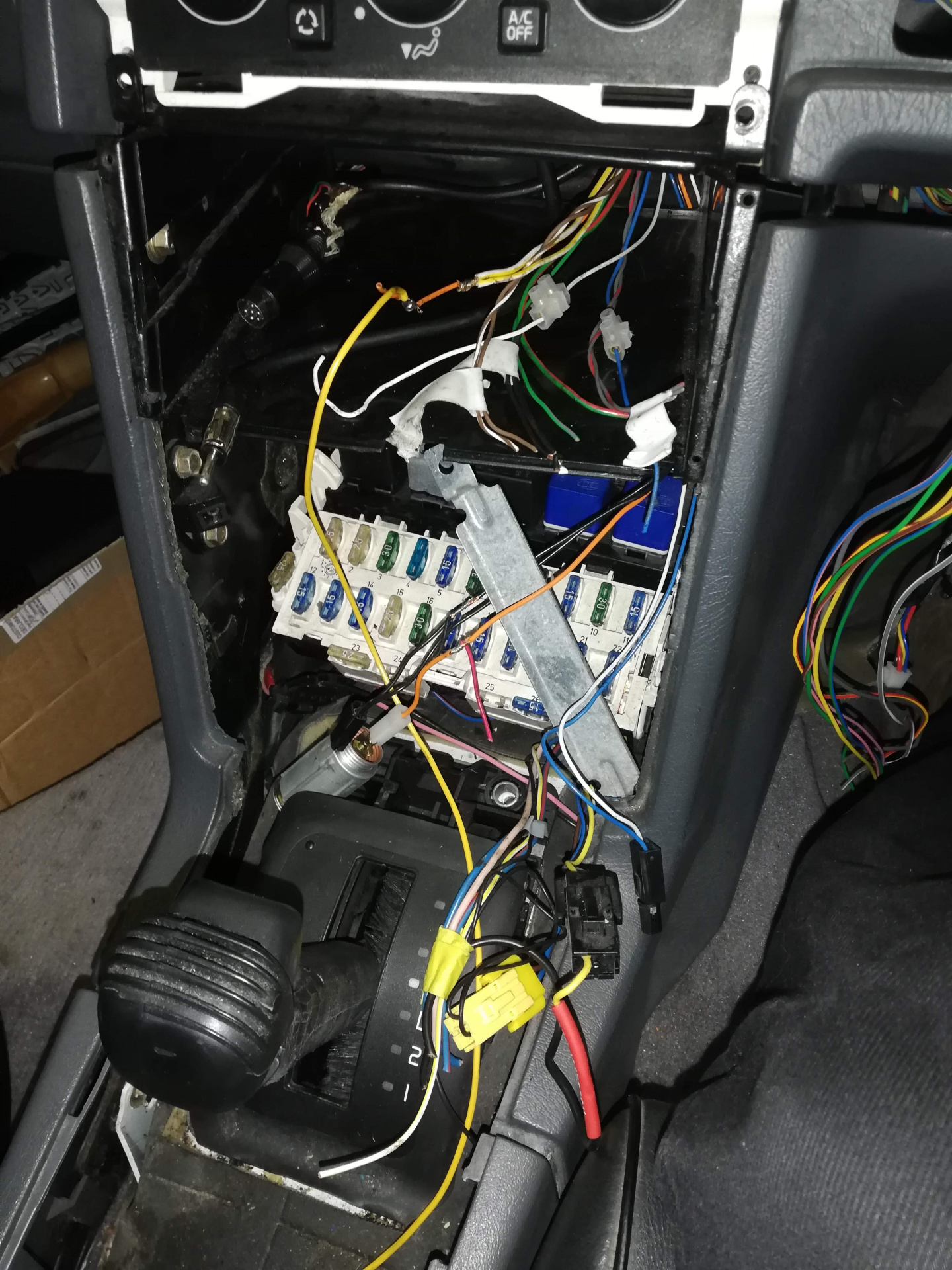
Terminal blocks, uninsulated wires.. it all had to go. I re-crimped the lot with ISO connectors with pigtails, so now any kind of headunit can be plugged in. the second white connector behind is for the dash tweeters. Will eventually replace the stock dash speakers with something better.
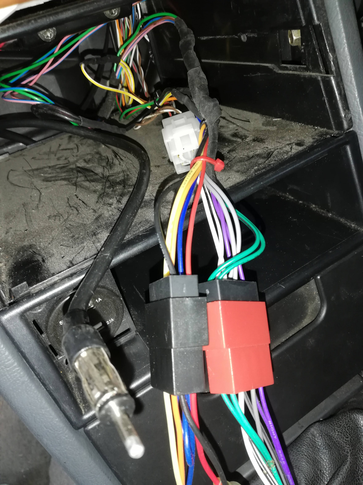
Much better.
I think I might have shown this before, but can't remember... onto some of the engine bay wiring.
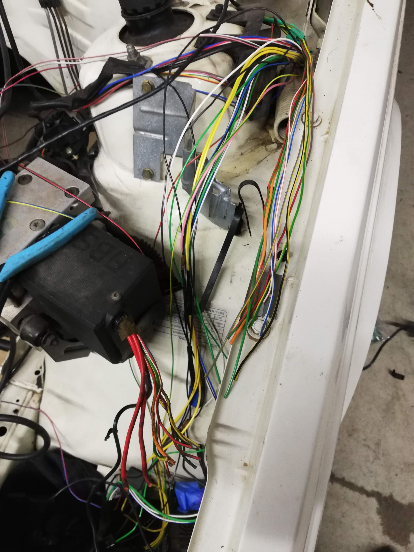
ABS Wiring
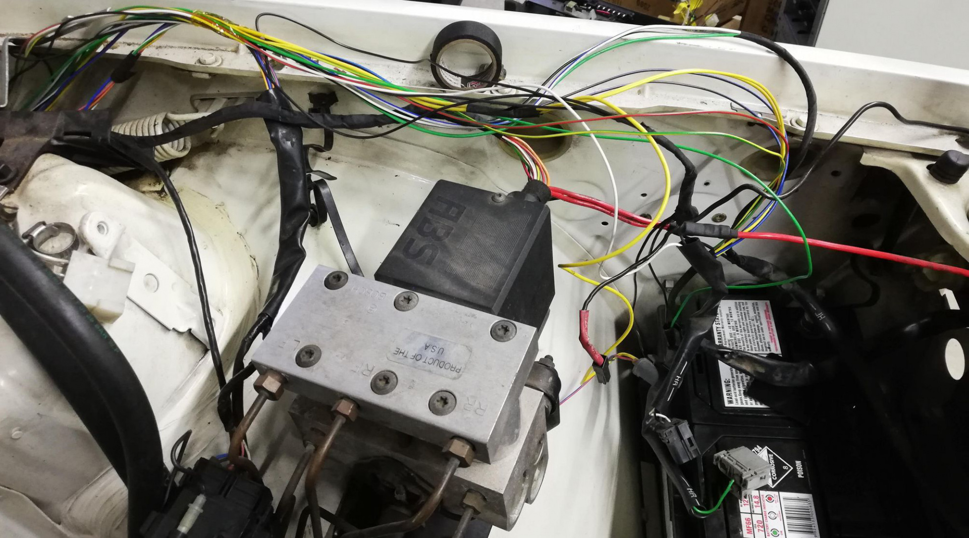
Chopped ABS wiring being re-crimped into a spare loom
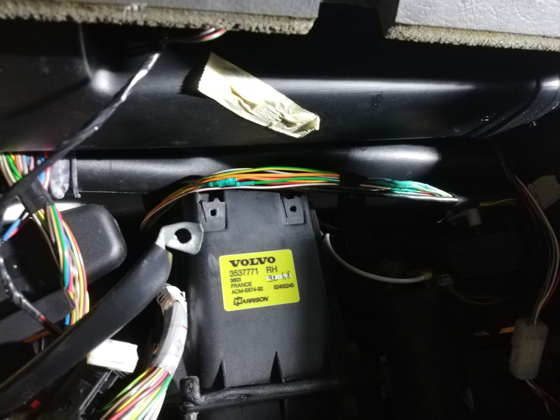
Relocated under dash
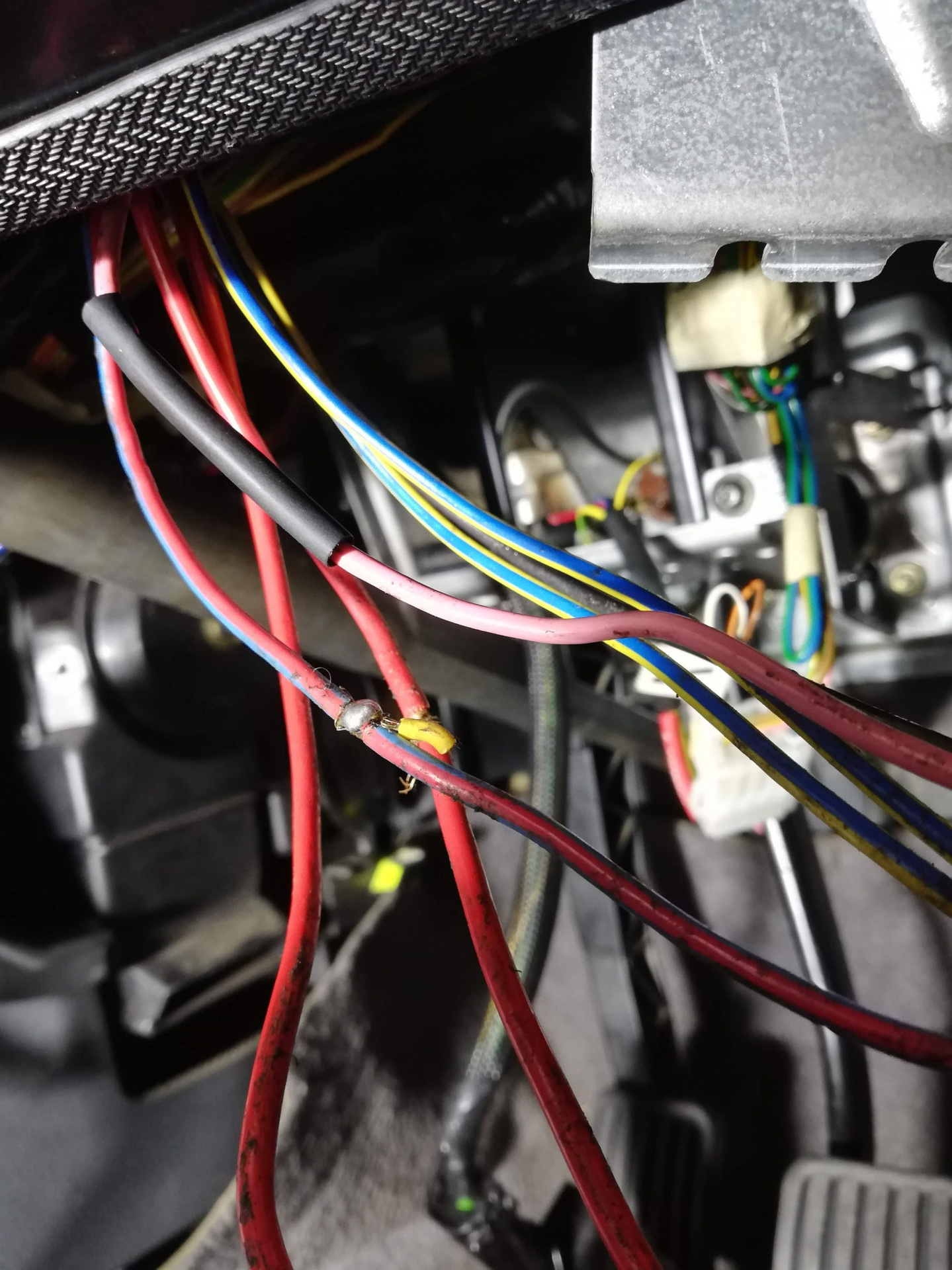
Me: "What even is this wiring?"
I'd say the above wiring was some spliced in accessories to the blue/red wire, which is ACC switched 12V. This was repaired, re-crimped and heatshrunk as can be seen in the image below. Minimal soldering used here - it's a more reliable connection for this purpose, and crimping is easier under the dash than mucking around with soldering irons in confined spaces, so it's a no-brainer in the end.
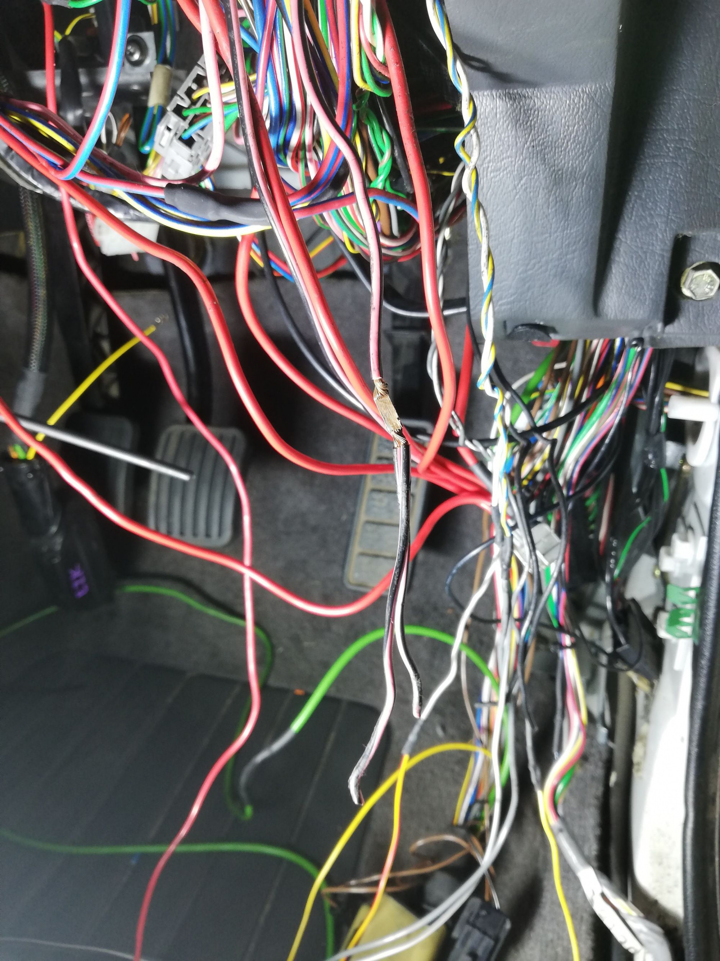
Figured out eventually that the cut dangling wire in the middle of the picture above was power for the separate stereo amplifier that lived under the steering column.
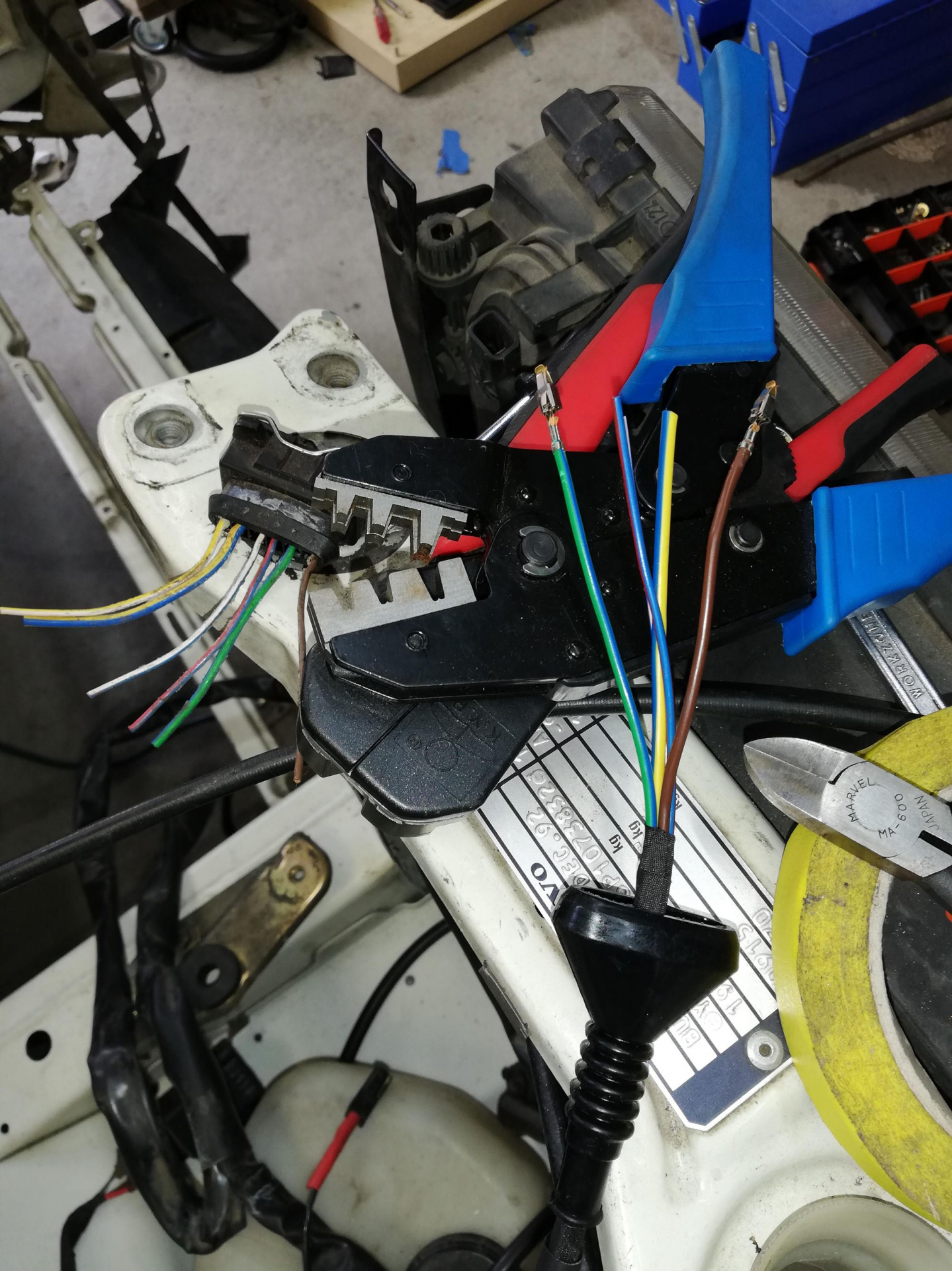
Wiring in a new MAF connector
I got a new Bosch Junior timer (the name of the connector series) plug to connect up the MAF on the drivers side. In the big pile of wiring looms I had, I located a set of wires with the 4-pin original plug so I was able to make a plug-and-play loom to go into what is originally in the car. The brown wire is sensor ground that goes eventually to the intake manifold ground point. A cut off original MAF connector can be seen up top left which was used as a visual reference to make sure I had the wiring positions right.
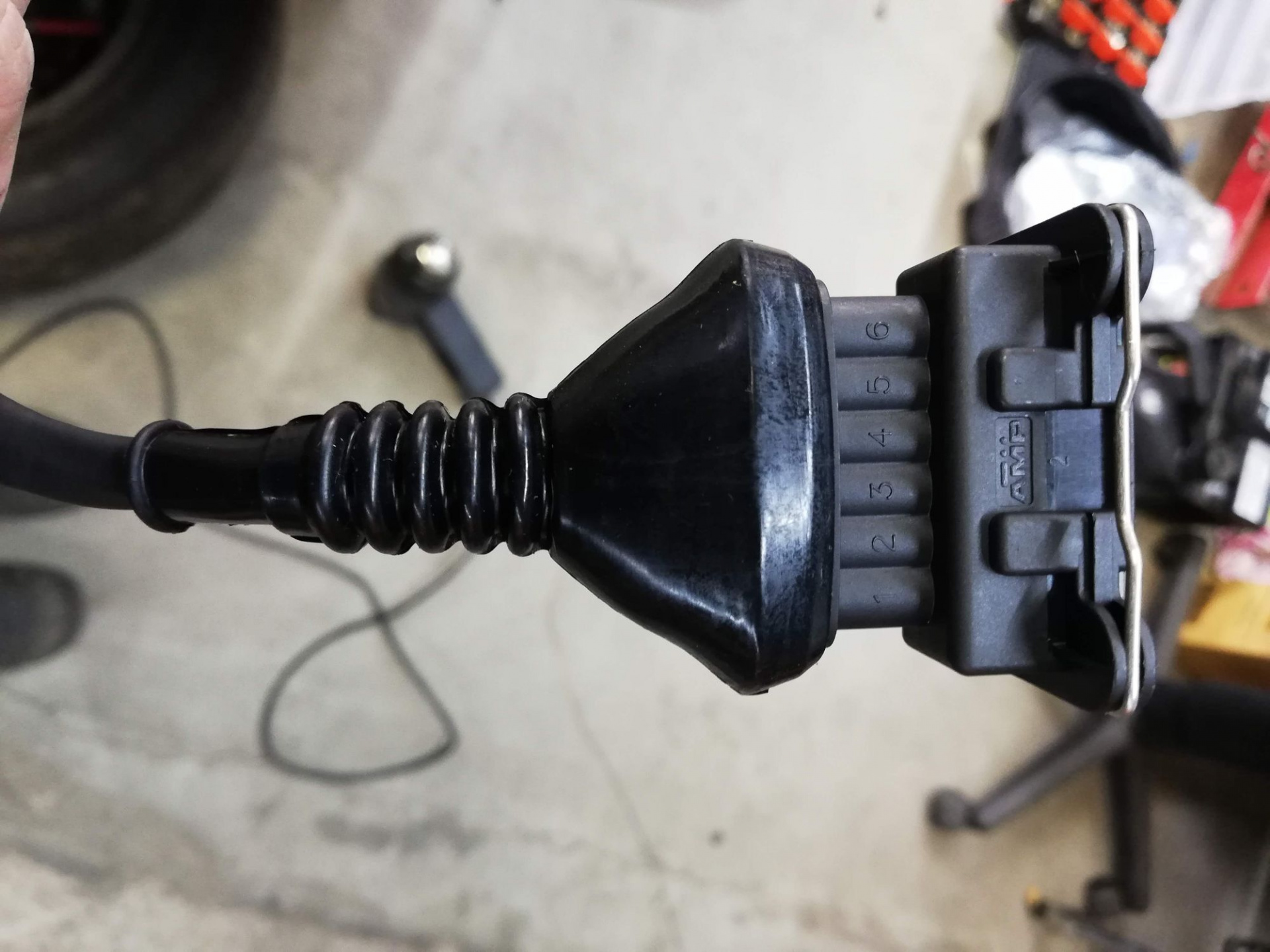
One newly wired in MAF connector!
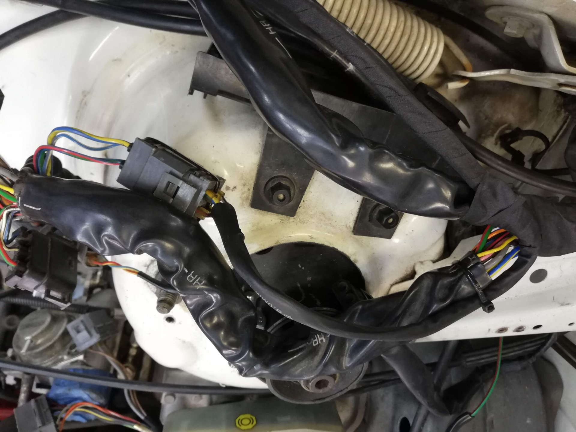
Still goes to the 4-pin but I was hesitant to cut that out completely
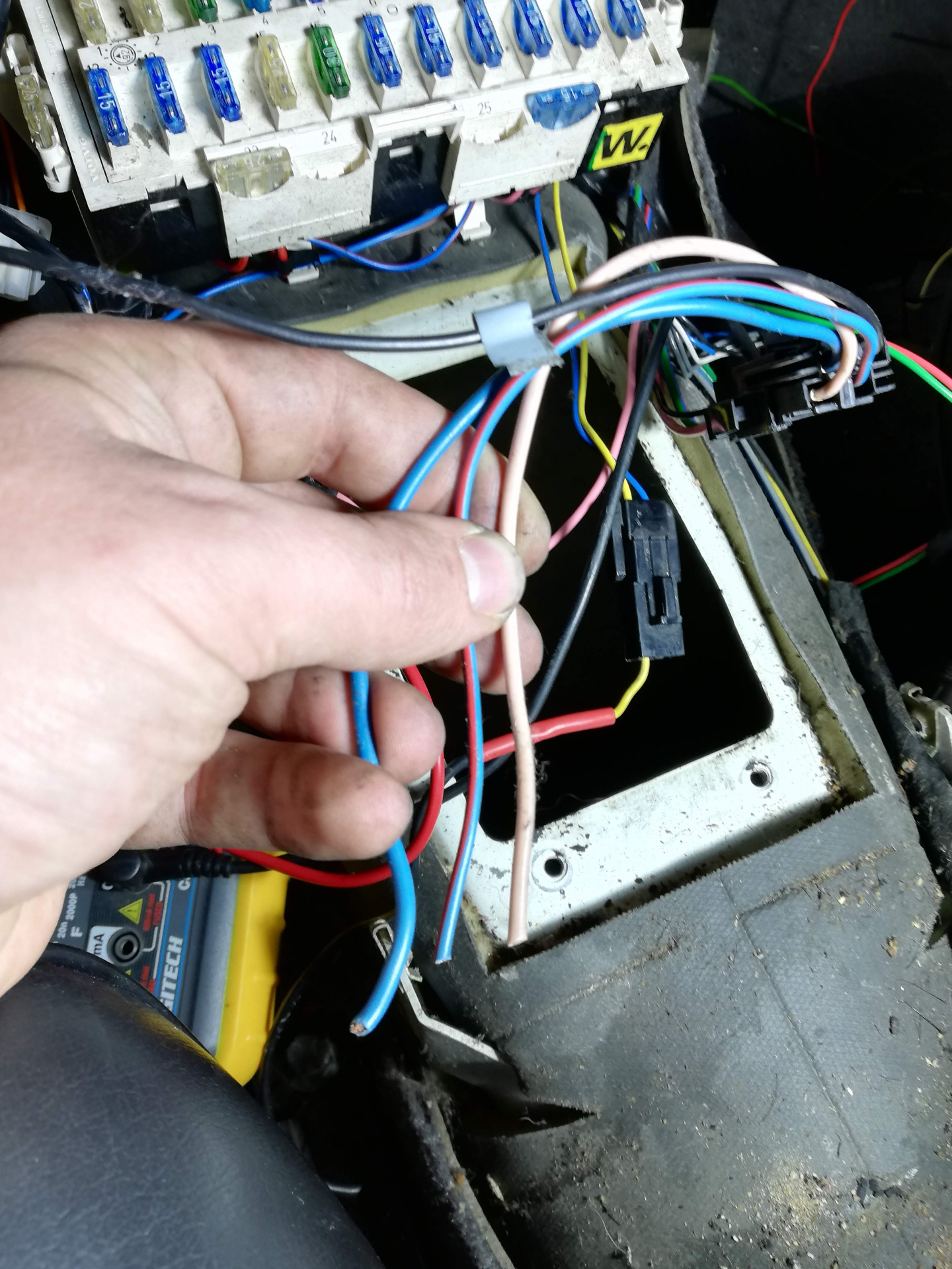
This cluster of wires is responsible for two things - the auto trans parking brake start inhibitor and the reverse lights. One needs to be terminated with a connector for the reverse light wiring on the manual trans, the other needs to be bridged as we no longer have a parking brake position!
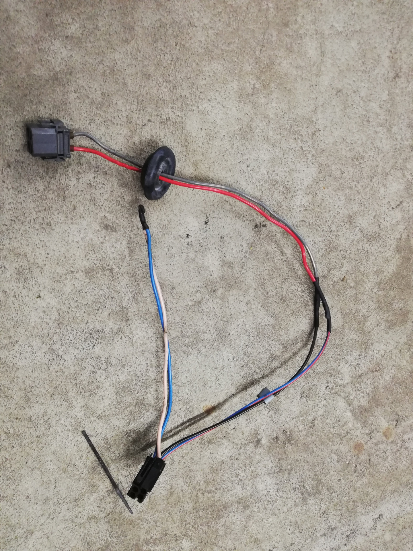
The end result. I just grabbed a suitable 4-pin connector to hook up to the manual transmission reverse connector, so ignore the mismatched colours.
For the main power wiring, I didn't have much original stuff to see how it was done before, so I made it up. I put a 200A breaker near the battery in case of serious shorting. placing it just next to where the ignition module goes. This was the first time I used rivnuts with my eBay special rivnut tool. So good.
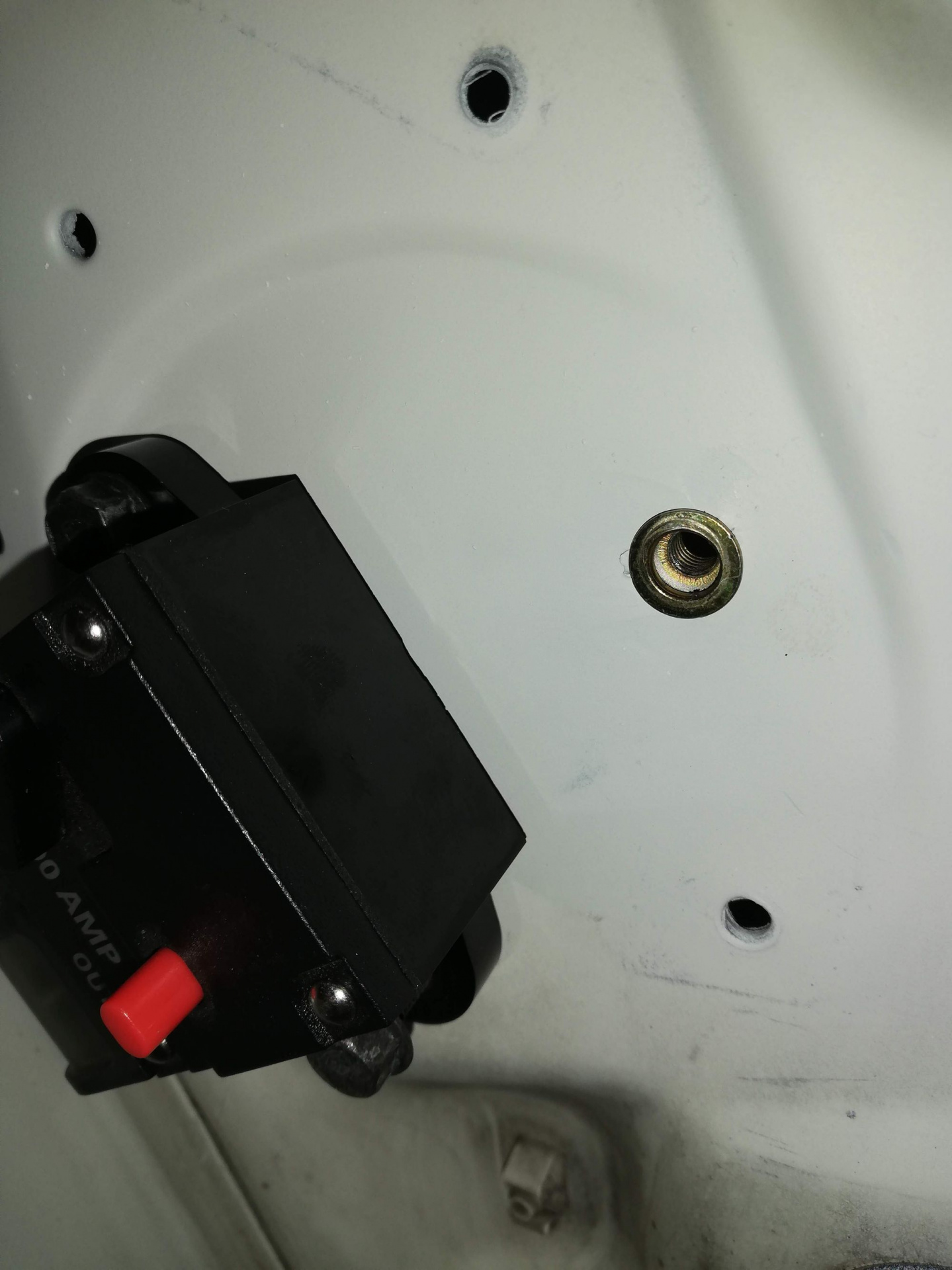
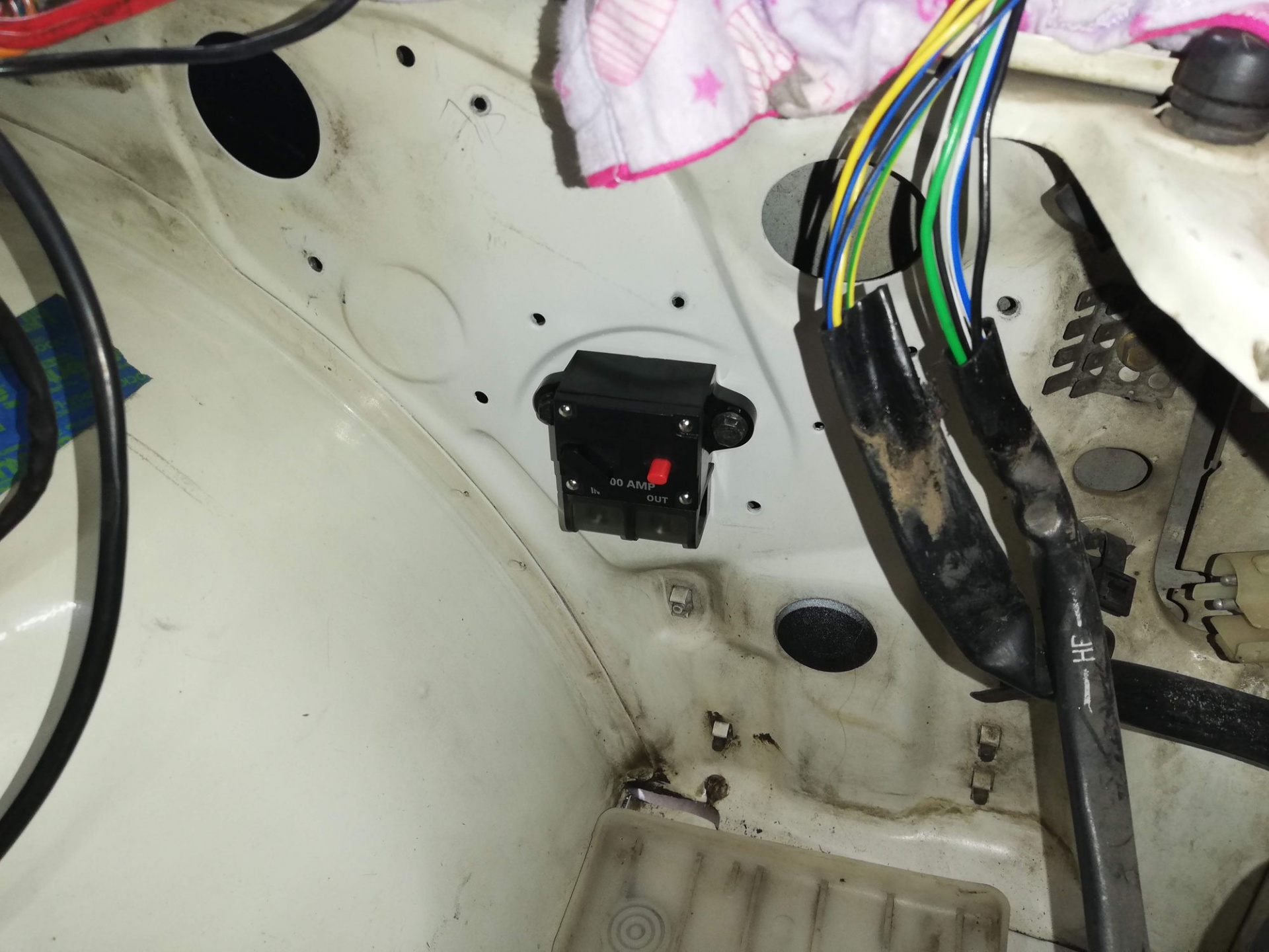
From there I'd run some 0-gauge wire to a distribution block somewhere which will then feed the cabin main 12v, the starter, and eventually, my old Jaycar stereo amplifier :) I gave this area a quick spray with some colour-matched paint before putting the rivnuts in.
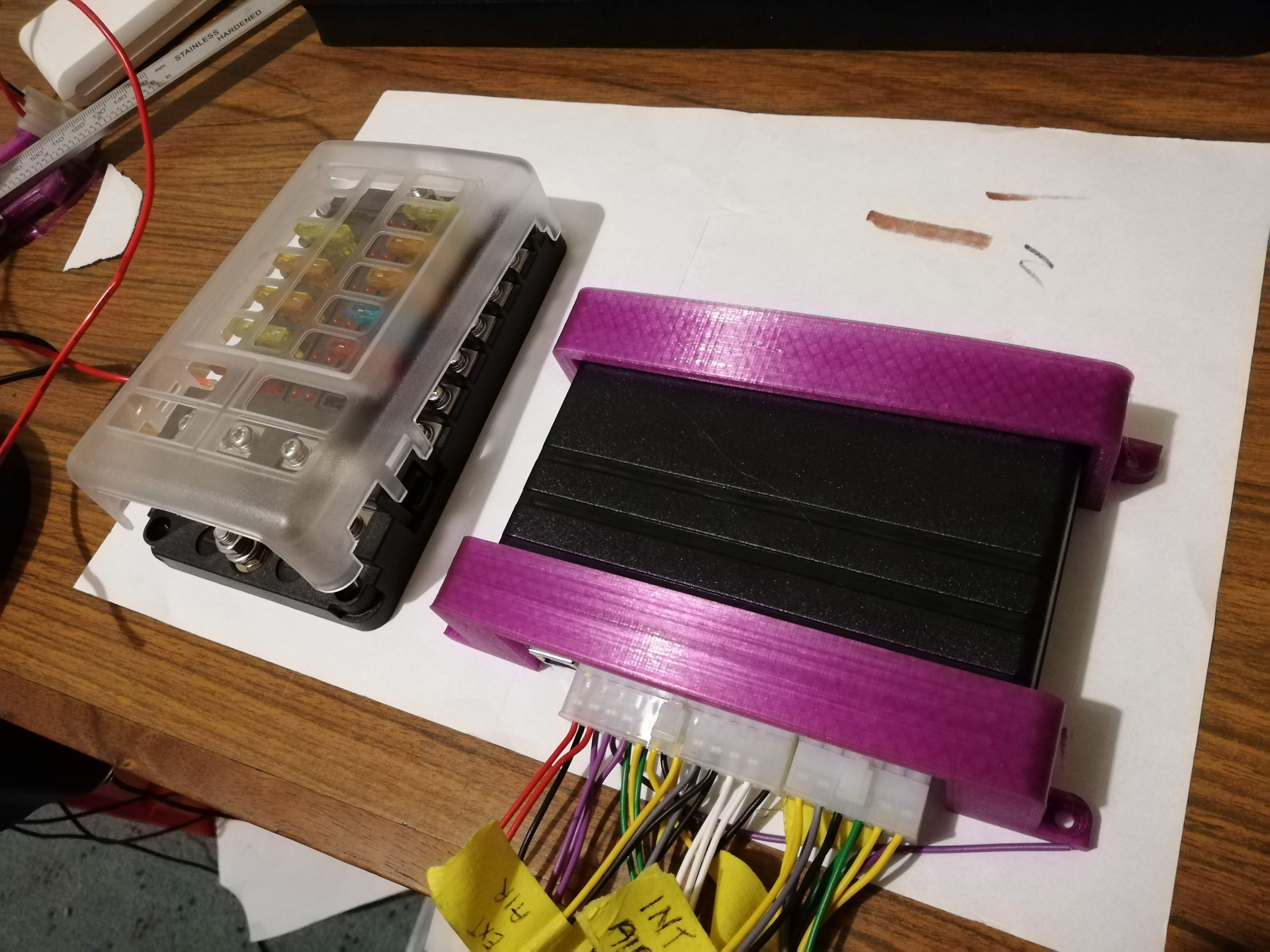
Mocking up units that I need to mount somewhere on an A4 piece of paper.
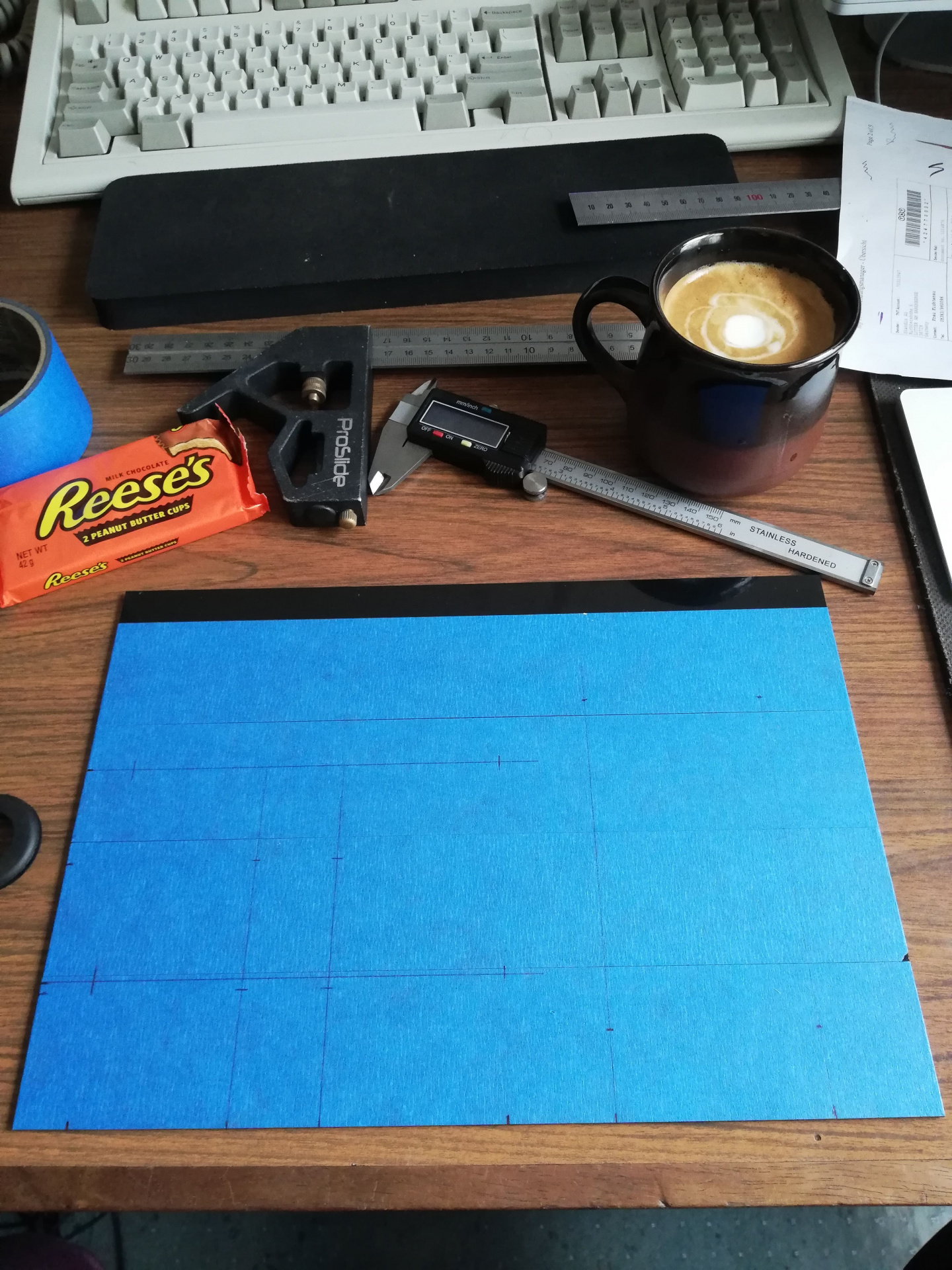
I got this A4-sized ABS 3mm sheet and laid some painters tape on it and started marking where I wanted to drill holes to lay things out. I realised I wanted one fuseblock that had 12v constant power as well as one with 12v switched, and a ground block too, so I ended up with two fuse boxes, one with an integrated ground block. The piece would be placed in the glovebox to allow easy access to the fuses.
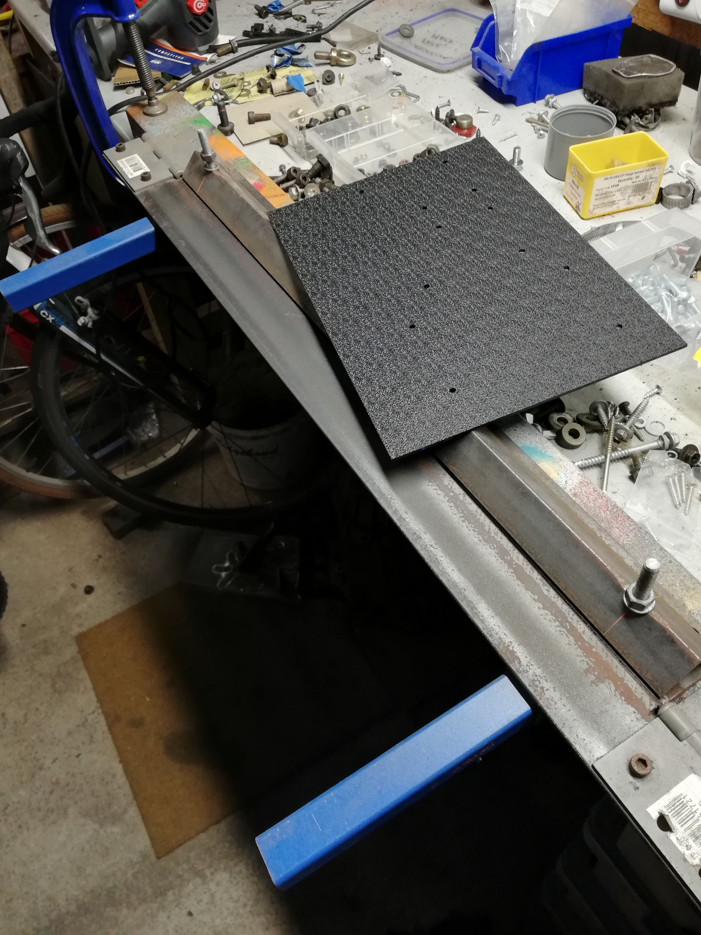
Once the holes were drilled out for the various components, I had a look at the size of the sheet in the glovebox, but it was a little too big. I had two options - either cut it down to the size of the back of the glovebox, or bend it to match the contour of the glovebox. I figured I could try bending it with some heat and my homemade sheetmetal brake and failing that, just cut it off.
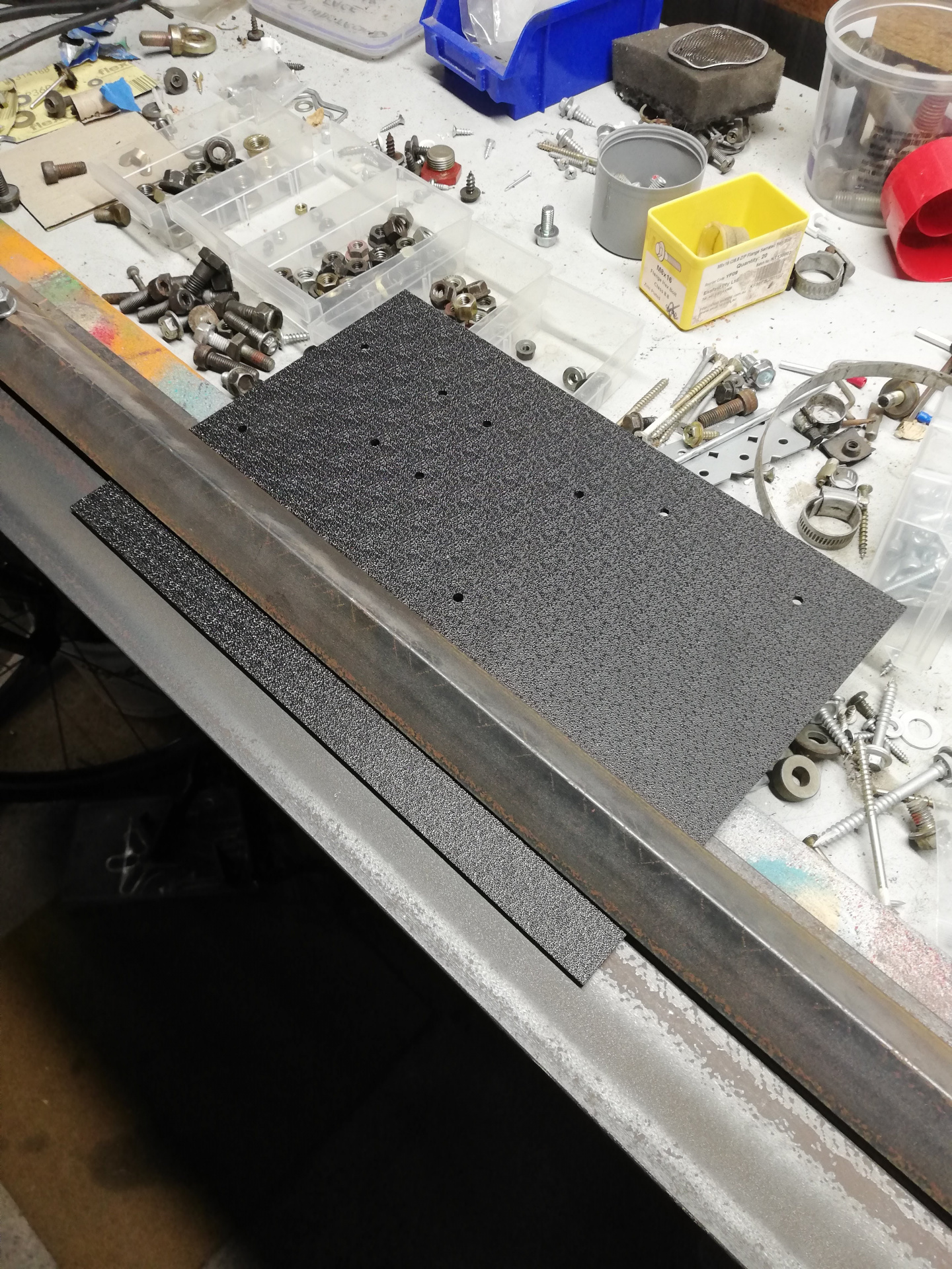
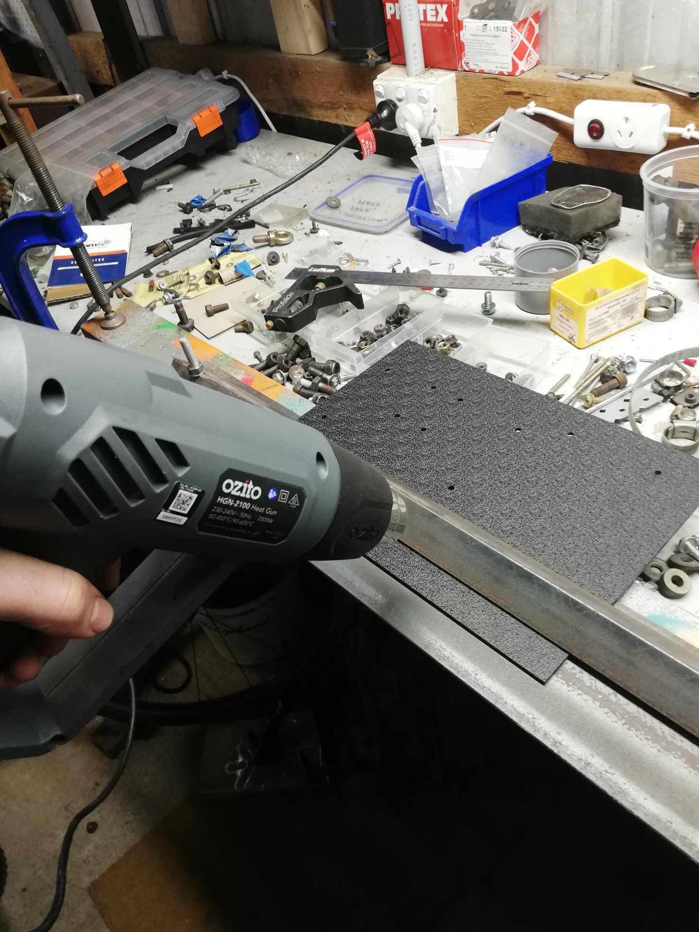
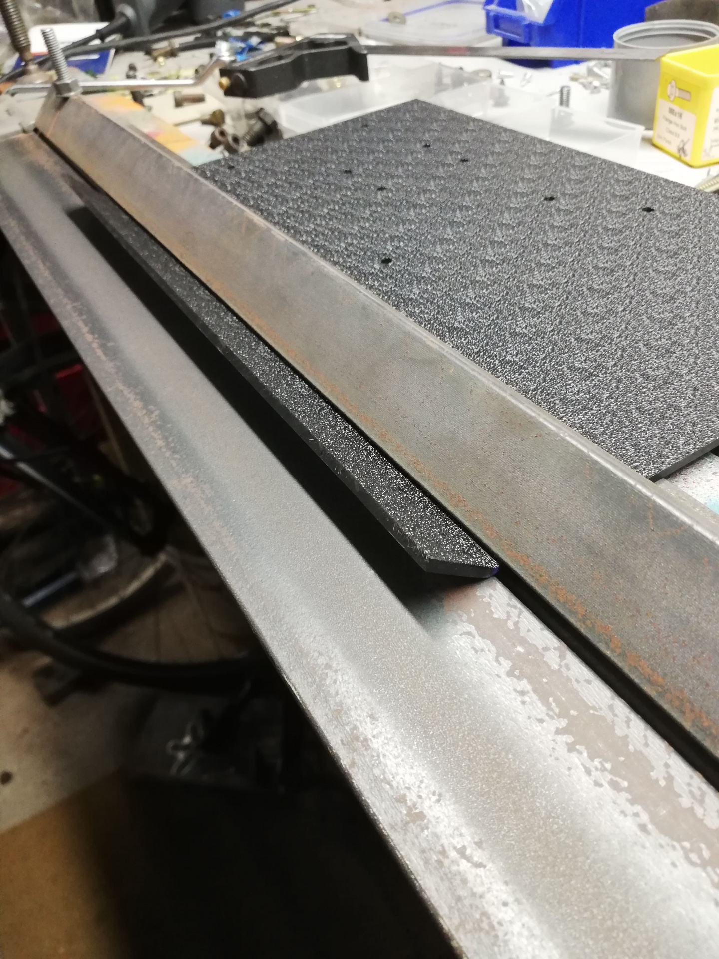
Very slowly keeping the heat on without melting it, but just enough to bend it up gently.
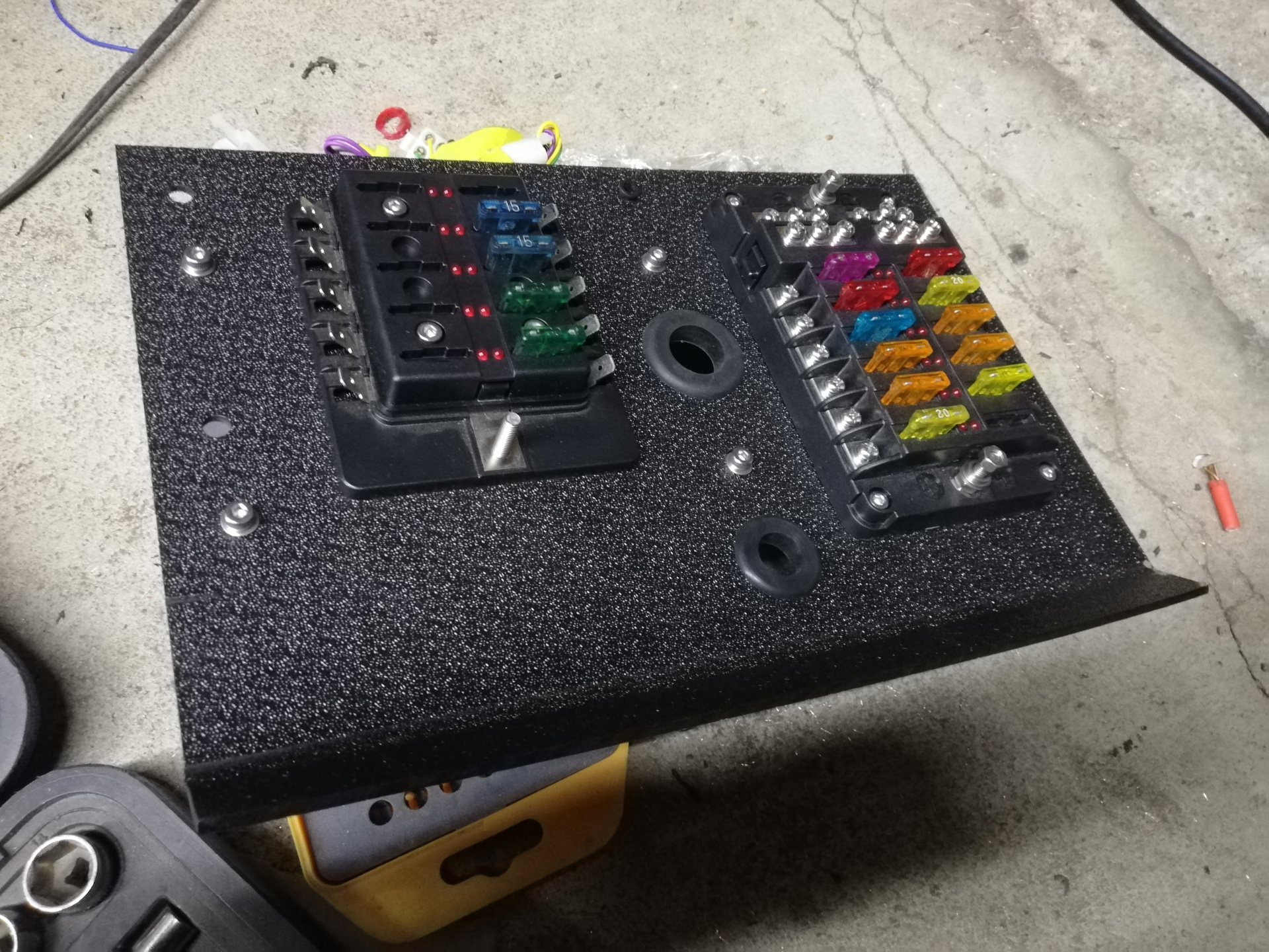
It's not perfect, but it'll do for a version 1.0. The UTCOMP unit is mounted on the back of this and I'll go into more detail on that in another post. With the fuse boxes laid out, we can dummy fit them in the rough location and start testing out the wiring and see if things turn on! Always a bit of a nervous time when you flick the battery on for the first time on a new project or a car you've been working on for years..
________________________________________________
Just wanna say a thanks to those reading and +1'ing the posts. It's been really positive to have some feedback on the project, good, bad or otherwise :)