Following
122s engine rebuild plus more - UPDATED 16 Sept - CC'ing the head
What engine is that?
- Edited

B20E, still with HS6 SUs. Not sure where the manifold is from, seems modern. Dual exhaust outlets and no preheat system.ramrod;c-161574 wroteWhat engine is that?
7 days later

Not bad, what is the compression ratio you are going with on the head and the squish volume? On my pushrod redblock builds I aim for 0.035' , makes it less likely to ping.
What cam will you be running?
- Edited
Vee_QueNot bad, what is the compression ratio you are going with on the head and the squish volume? On my pushrod redblock builds I aim for 0.035' , makes it less likely to ping.
What cam will you be running?
The compression ratio and squish is yet to be measured. Squish will be pretty easy to measure, I think/hope. Hopefully it comes out ok. The machine shop was reluctant to assemble to check. I have thought about custom head gasket too. Measuring the capacity of the chamber might be a bit more of a challenge. Off to ebay to see how much a pippet (I think that's what I need) is. (edit: pippette is what I was thinking of, may be able to use a syringe to get close)
The cam is a K reproduction from CVI, says made in usa on it.
I plan on rebuilding a second head at a later date. I have a mate that will port it. Prob don't need a better cam till that happens.
I live in the city so I kinda want to stick with the SUs.
You may find the K requires a lot of rpm to deliver (that is if you've not had experience with the K). The D with an appropriate 123 programmable electronic ignition will deliver mid range power and torque.
- Edited

K and D cams for a B20 are very similar.
http://www.1800philes.com/ianr/_superlist_grinds.html
The K was used in B20E engines. I had a K cam in my 144 years ago, and it was very good for a daily driver - there was good idle, and it wasn't a pig below 2200 RPM, like the later (bigger) cam in that car was.
I run an aggressive cam on my 122 b20 compared to stock, and it is no harder to drive than a modern 16v s40 Volvo, I'd even say it's equal. So sure it doesn't have all it's torque at 1500rpm and you can't bog it down, but you shouldn't anyway!
8 days later
I got a little further today.
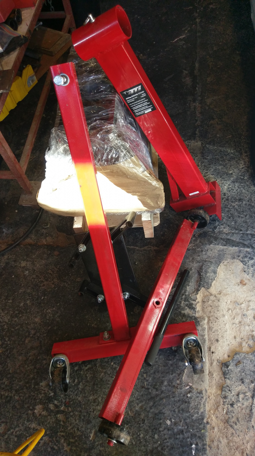
I dug out the engine stand.
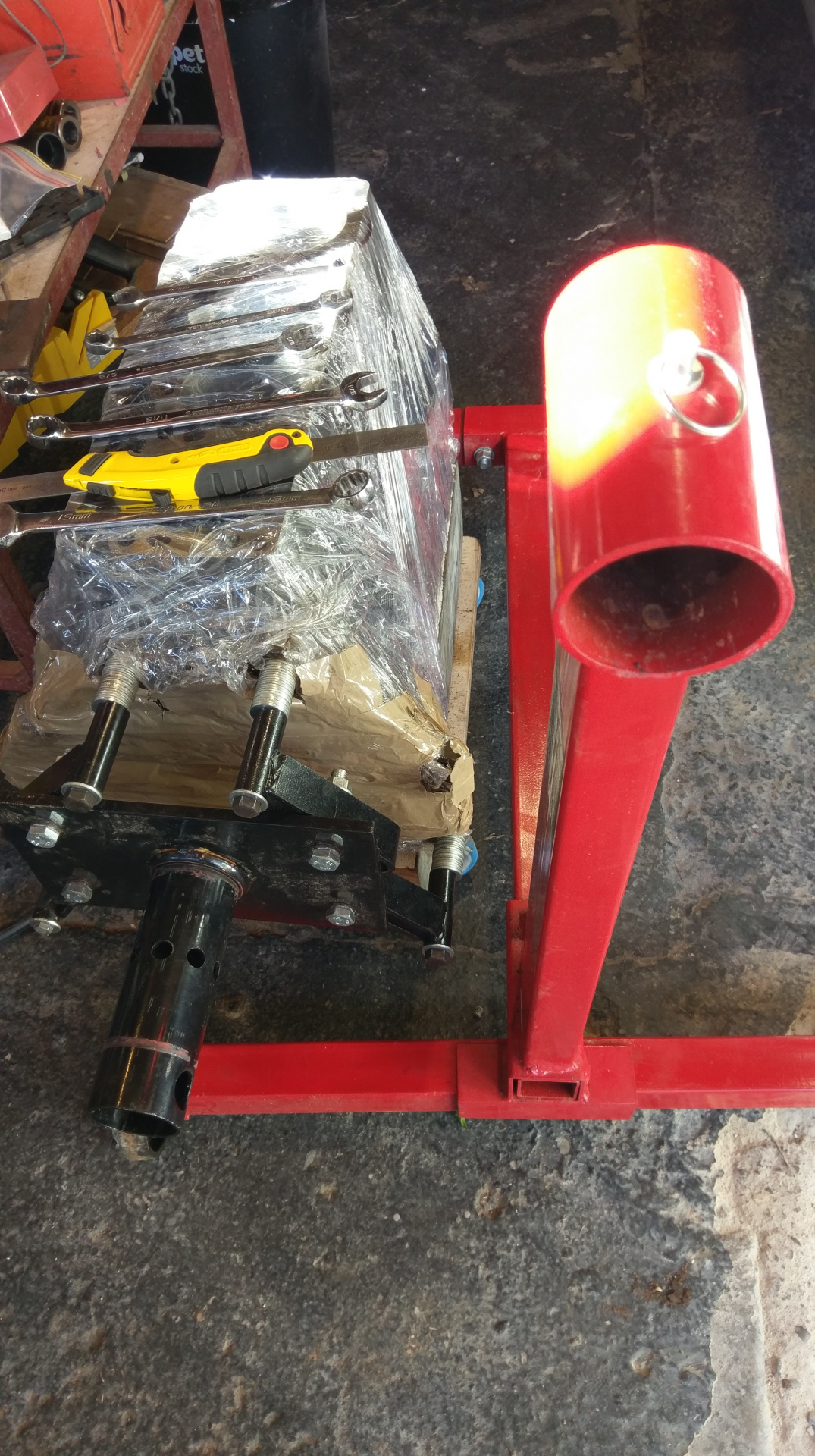
Got it mounted to the block.
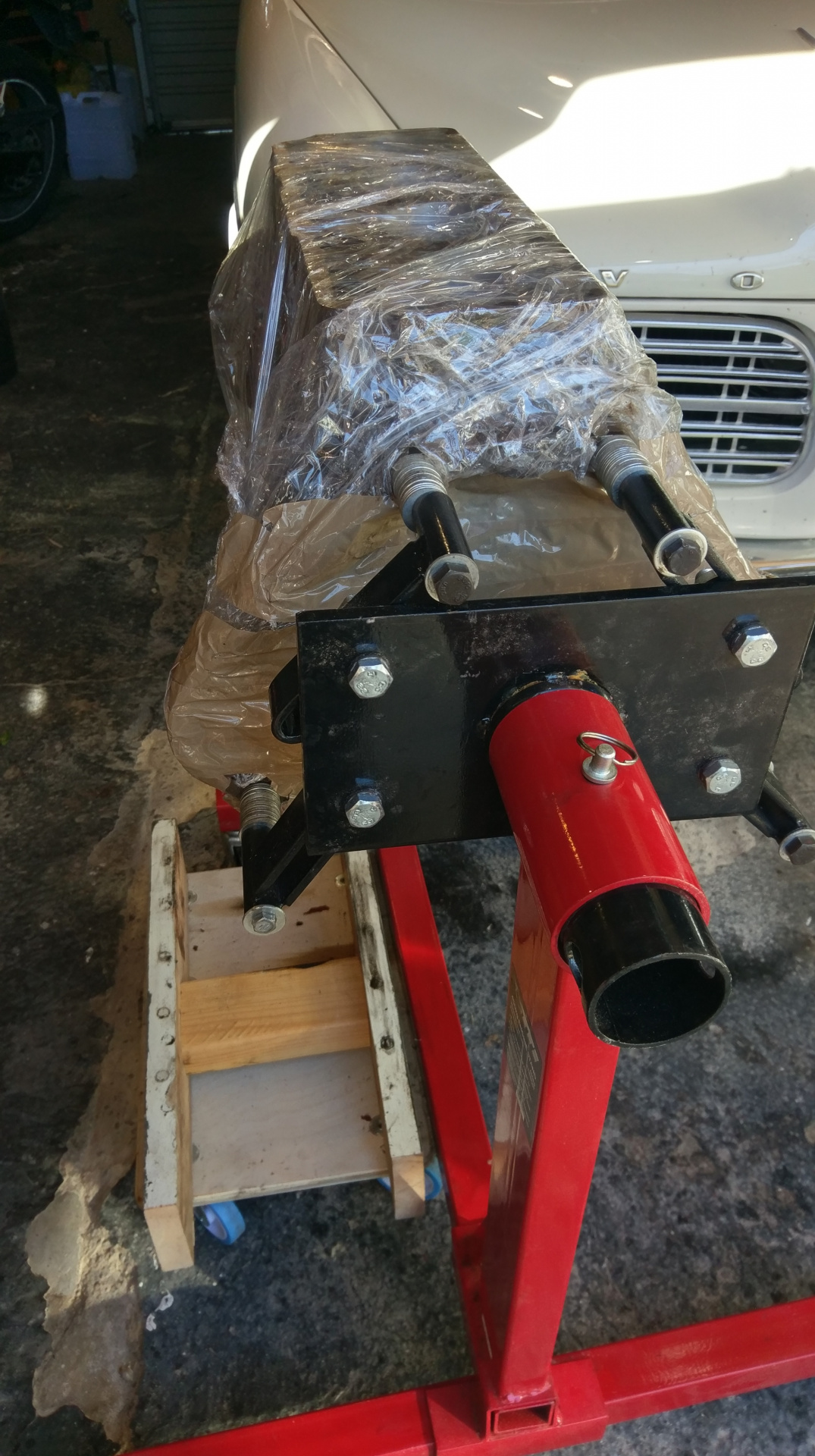
With some help from my better half to lift the assembly in place.

I wiped down the main journals with acetone and blew with compressed air. The block is pretty clean as I got the machine shop to clean and wrap. Worth the sixty bucks.
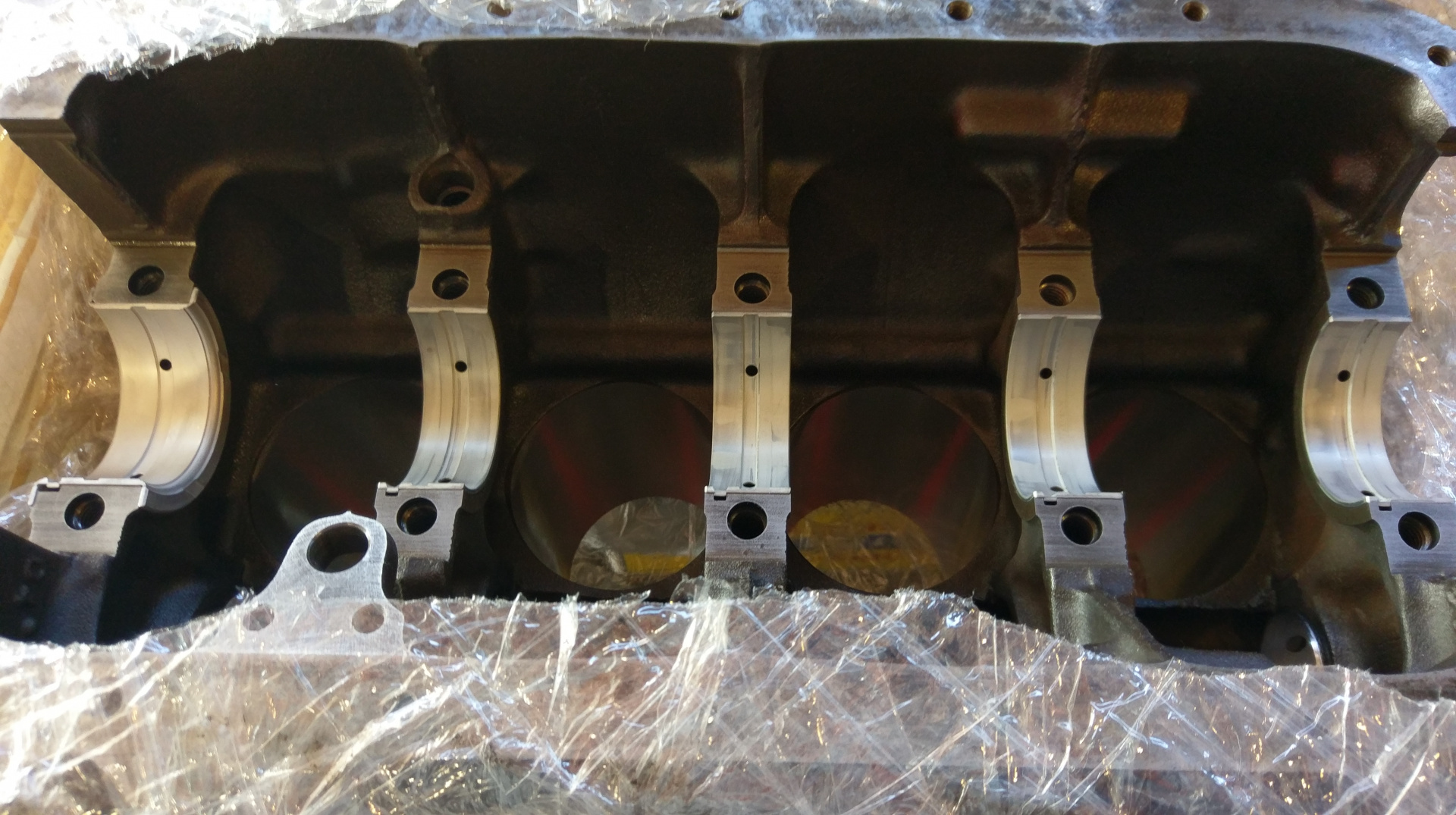
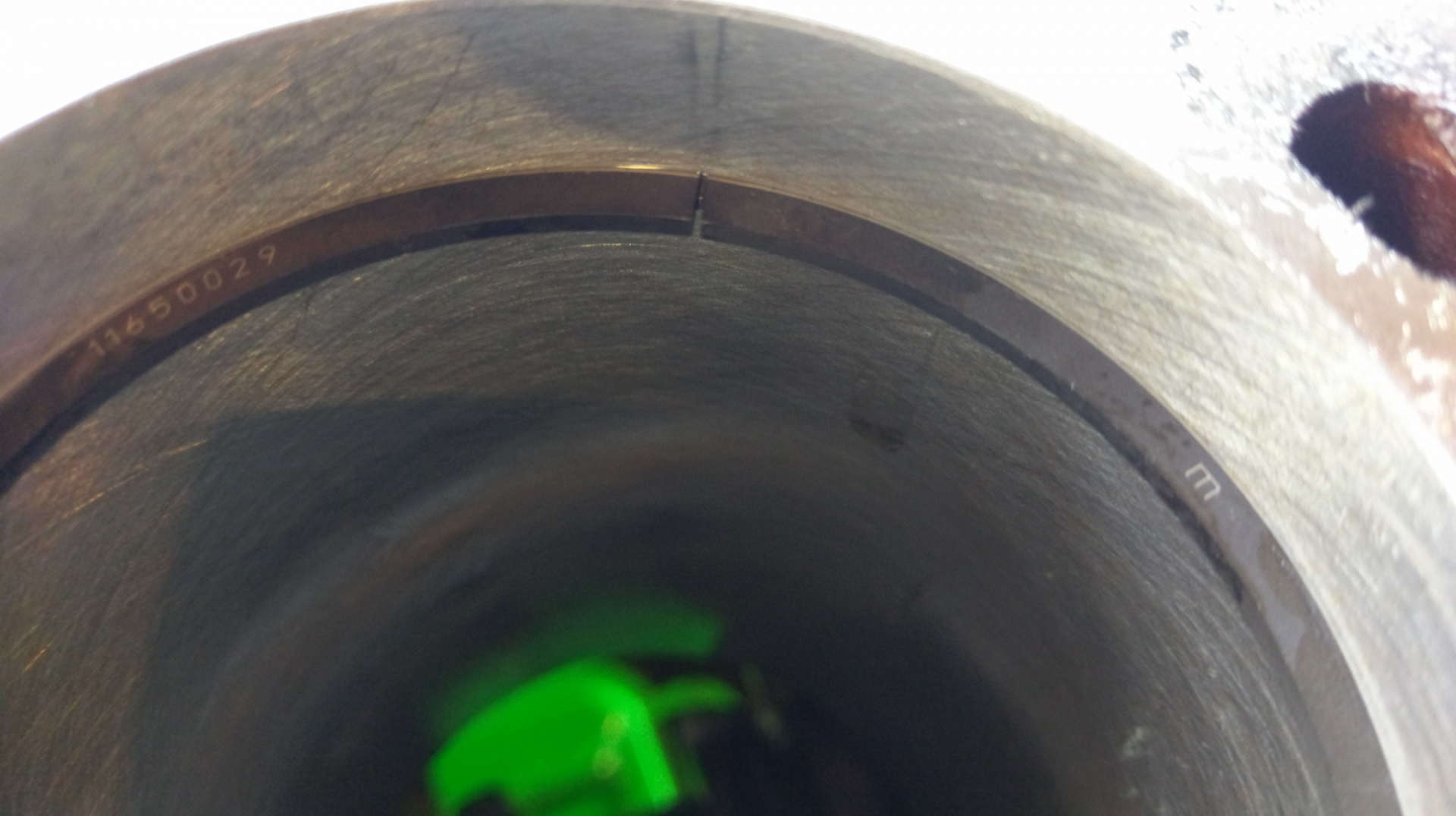
Main shells in the block.

It came cleaned but oiled. Wiping down with a soft clean rang and acetone and blowing clean including the oil ways. the edges of the oil ways have been nicely deburred. The efforts of balancing can be seen with the linishing marks on the first counter weight and near no.4 big end journal.
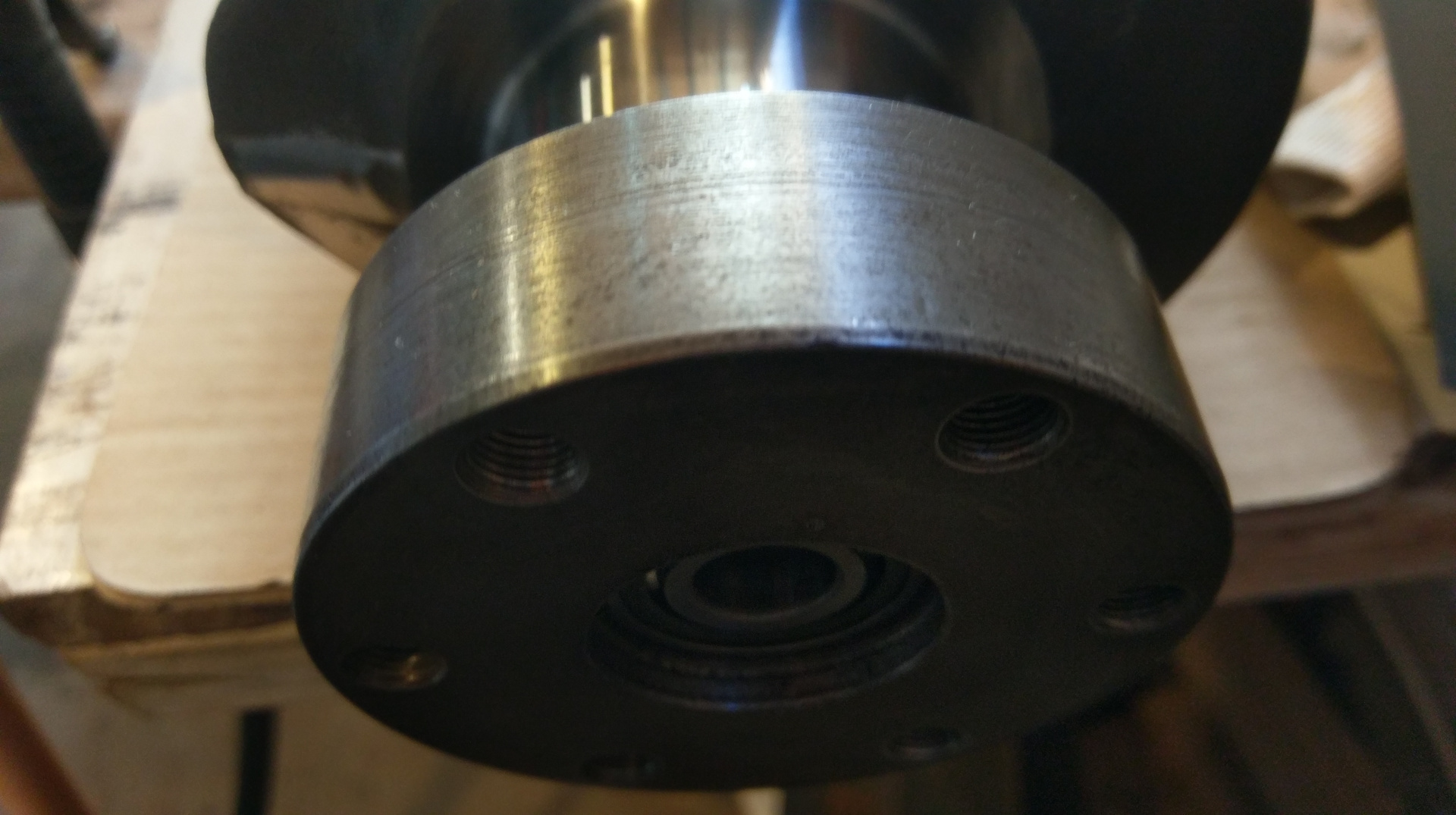
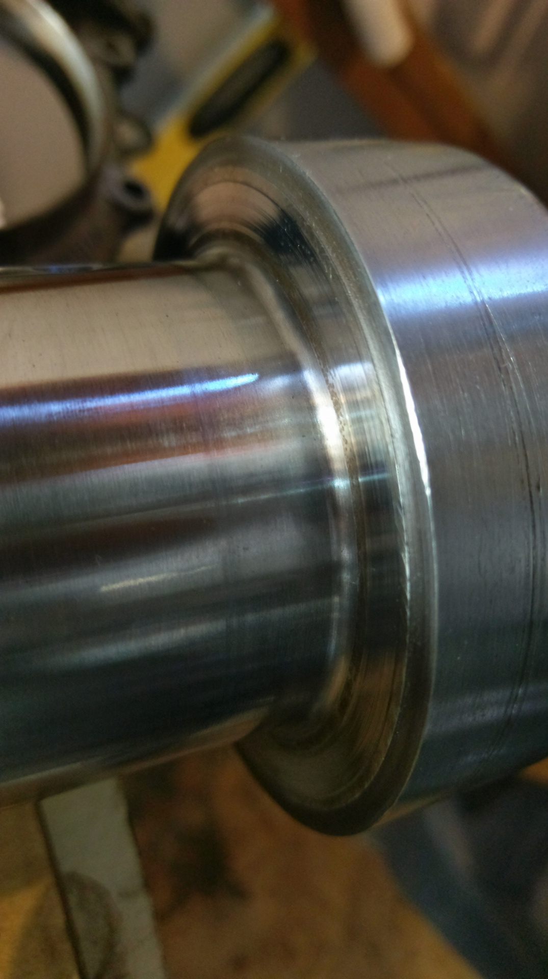
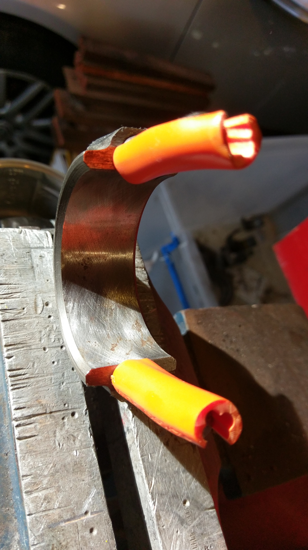
the main seal surface doesn't look great. I hit it with some 1200 wet and dry and metho.

That's a bit better. I will have to remember to leave the main seal proud so the seal runs in the best area.
It can be seen in the last two pics that the thrust surfaces only just cleaned up.
On the uncleaned rear main housing where the seal last sat. It should be ok to leave it proud by a mm or two.
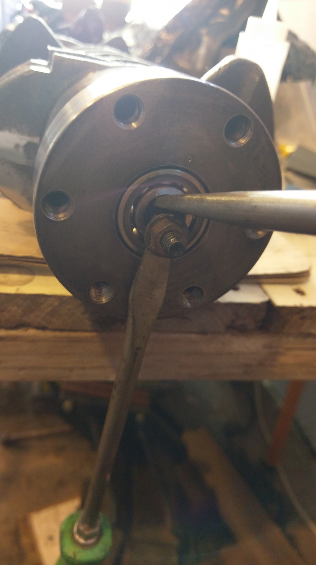
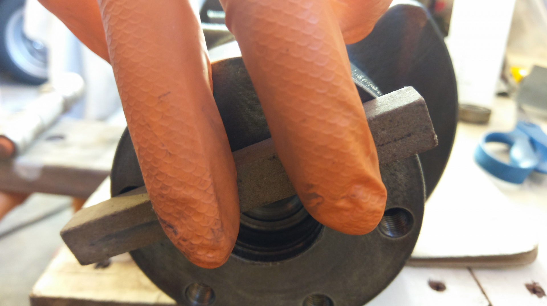
Extracting the spigot bearing without a puller. Grease (or bread if the grease gets though the sheilds) and a punch works fine too.
Giving the flywheel mounting surface a light stoning to ensure there are no raised burrs or dings.
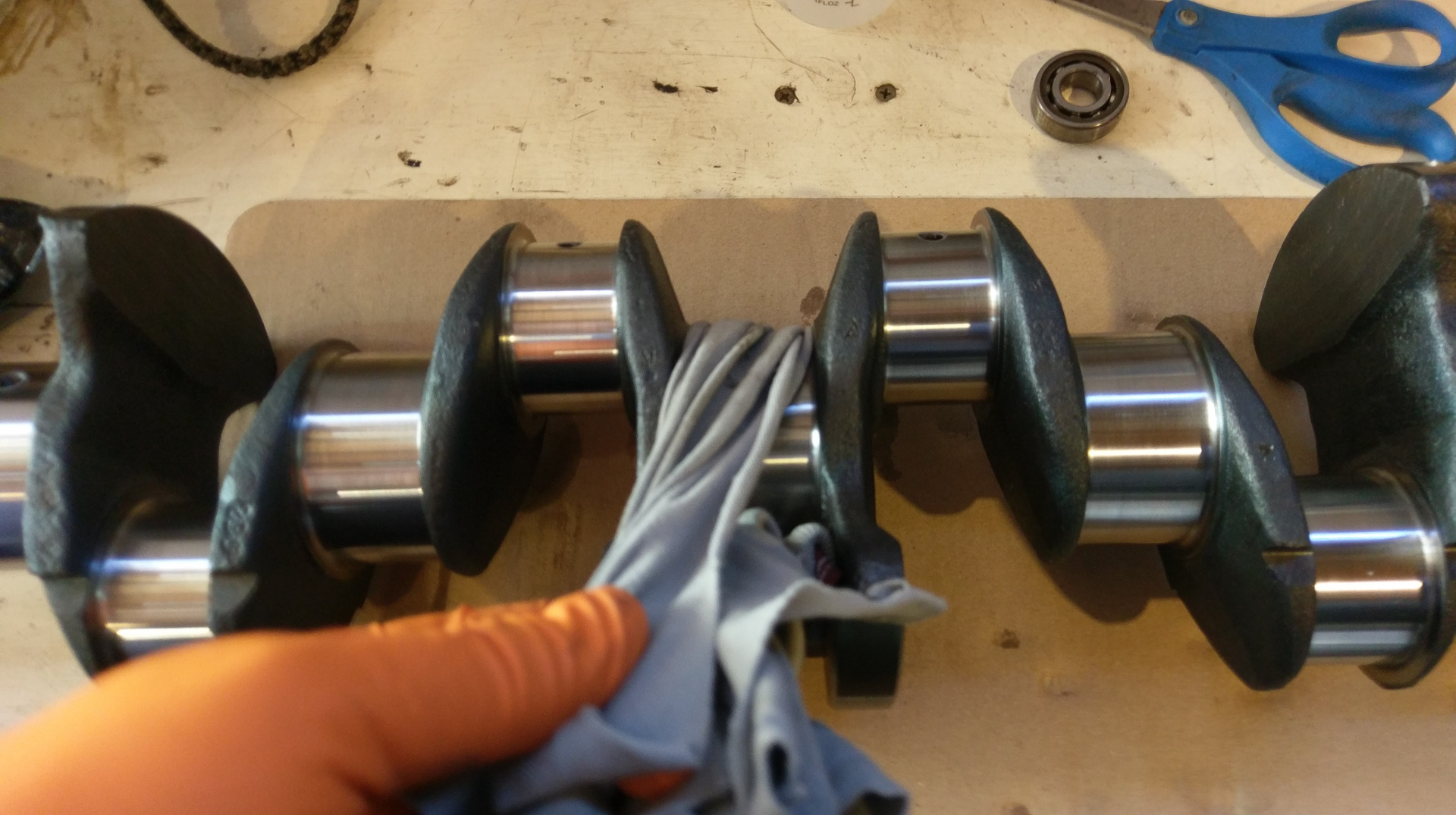
Giving all of the journals another clean with acetone and a soft cloth.
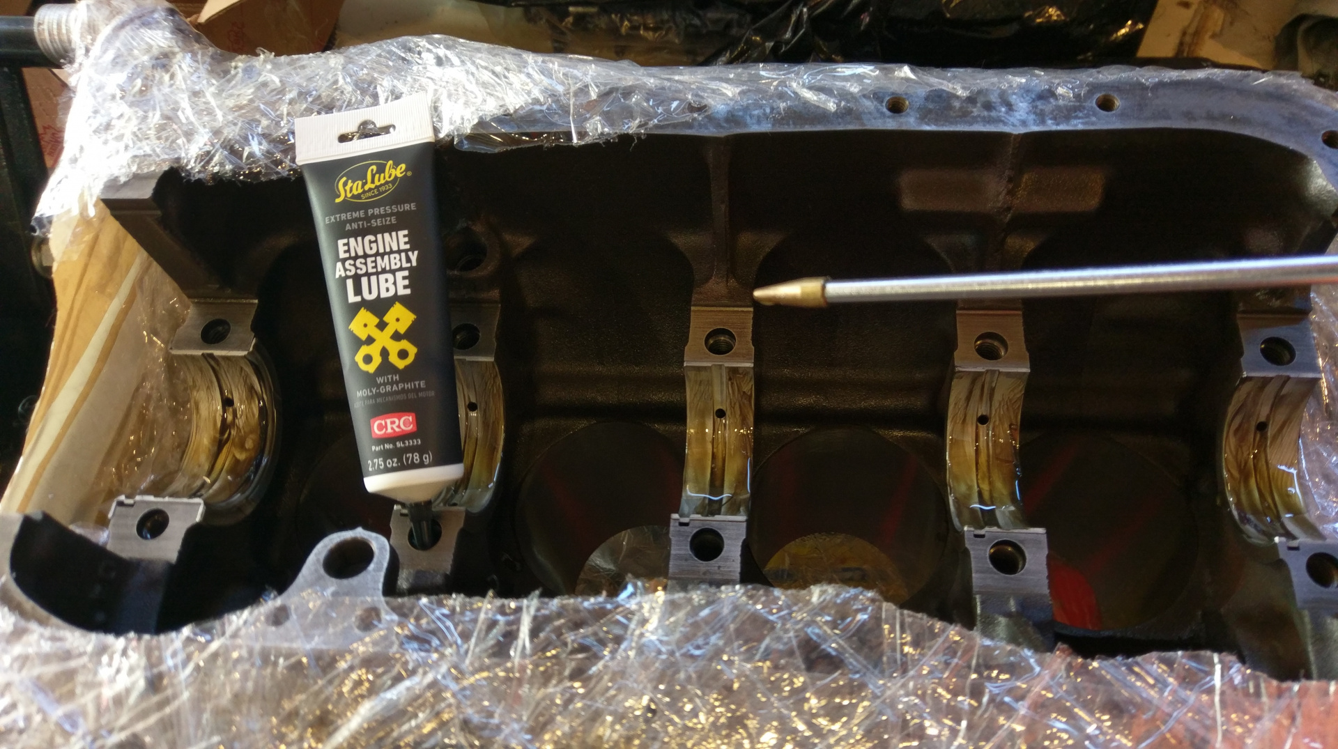
Adding some assembly lube and oil to the main shells in the block.

Gently placing the crank where it is supposed to be.

Adding some assembly lube and oil which I mix into a slippery goop with my finger.

All the main caps on and just nipped up. I turns by hand, which I guess is a good sign. I discussed with the machine shop if I should plastigauge it or not. The response was, if the were gong to assemble it for me the consider it fully measured and wouldn't themselves. They did assemble, torque and measure the bearings and grind to suite.
That's it for today, back inside to find the torque settings.
Hopefully tomorrow I will have time to get stuck into putting the rods/pistons in.
Thanks,
-Todd

Great detail and pics, looking great.
If you're worried about the rear main seal surface, you could consider fitting a Speedy Sleeve.
Angus242164Great detail and pics, looking great.
If you're worried about the rear main seal surface, you could consider fitting a Speedy Sleeve.
Thanks Angus. I think the sealing surface will be ok this time as long as I line up the sealing surface on the best portion of the surface.
I tweaked my back back pretty bad while trying to move the crank around while I was too far away. no work on Sun., spend the day laying on my back.
I am open to requests of pics of specific parts of the process while it is still apart.
-Todd
In response to the cam discussion I did a lot of reading and comparing grinds, costs and many reviews. I think for cost and performance most people won't go wrong with the D grind. I am planning on rebuilding my second head and having it ported. From what I can tell, the K grind is a reasonable choice with this plan.
I plan to keep performance mods within the capabilities of the SUs as I will be driving in the city a lot and think they are well suited to this.
There are many threads that are dedicated to cam choices so we don't need to go to deep into it here. Thanks.
I started one but, honestly I would talk to Clive cams and not just go with stock cams that suited a long time ago. Once again this thing about city driving, my b20 with nearly 11:1 and twin Weber's and big cam is no worse than a modern car, but too many people are scared by others saying it makes cars less drivable.
Nice details and I agree on the speedy sleeve, Cummins supply them for every crank seal change even.
- Edited
For now I am sure it will work fine with the K cam. While it may not appear so, I do have a limit on what I can spend. In the future, changing the cam while the head is off will be pretty easy. The motor in my car now prob has a worn out K cam, and worn out everything and it still performs ok for what it is. At the moment my car is too smokey for all but emergency use on the road. My primary need at the moment is getting that sorted.
If my polish job on the rear main surface is not enough, I will attend to it when I do the future 5 speed project. Which rates well above performance mods.
Has anyone felt the need to try adding dowl pins for aligning the front and rear housings? It seems they need aligning with a special tool or seal force, which I expect is the default method.
Cheers,
-Todd

I use the seal force and then nip a couple of bolts. Then I measure the crank to deal housing edge, and tap the seal housing slightly to align as best I can in the right direction/s. I use a Mitutoyo calliper but other methods would be close enough too l suspect. Then I have a close look to see any obvious distortion on the seal lip just in case. Only takes a few minutes to get quite accurate. I have not had one leak after about ten times doing it this way. I also use the black petmatex Shellac based aircraft gasket goo on the gasket face.
Good to see a b20 being built. The costs add up I know. I am about to do one to get a 145 mobile again. B20 engines are much better with an extra gear on the box. They don't have to be fast to give you a big smile. They just sound and feel good.
Great write up
7 days later
Well, the back put me out of action for a bit, hopefully can get stuck in on the weekend.
- Edited
I made it out to the garage today and got stuck into the next step.
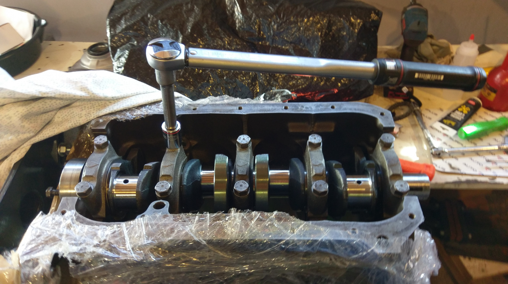
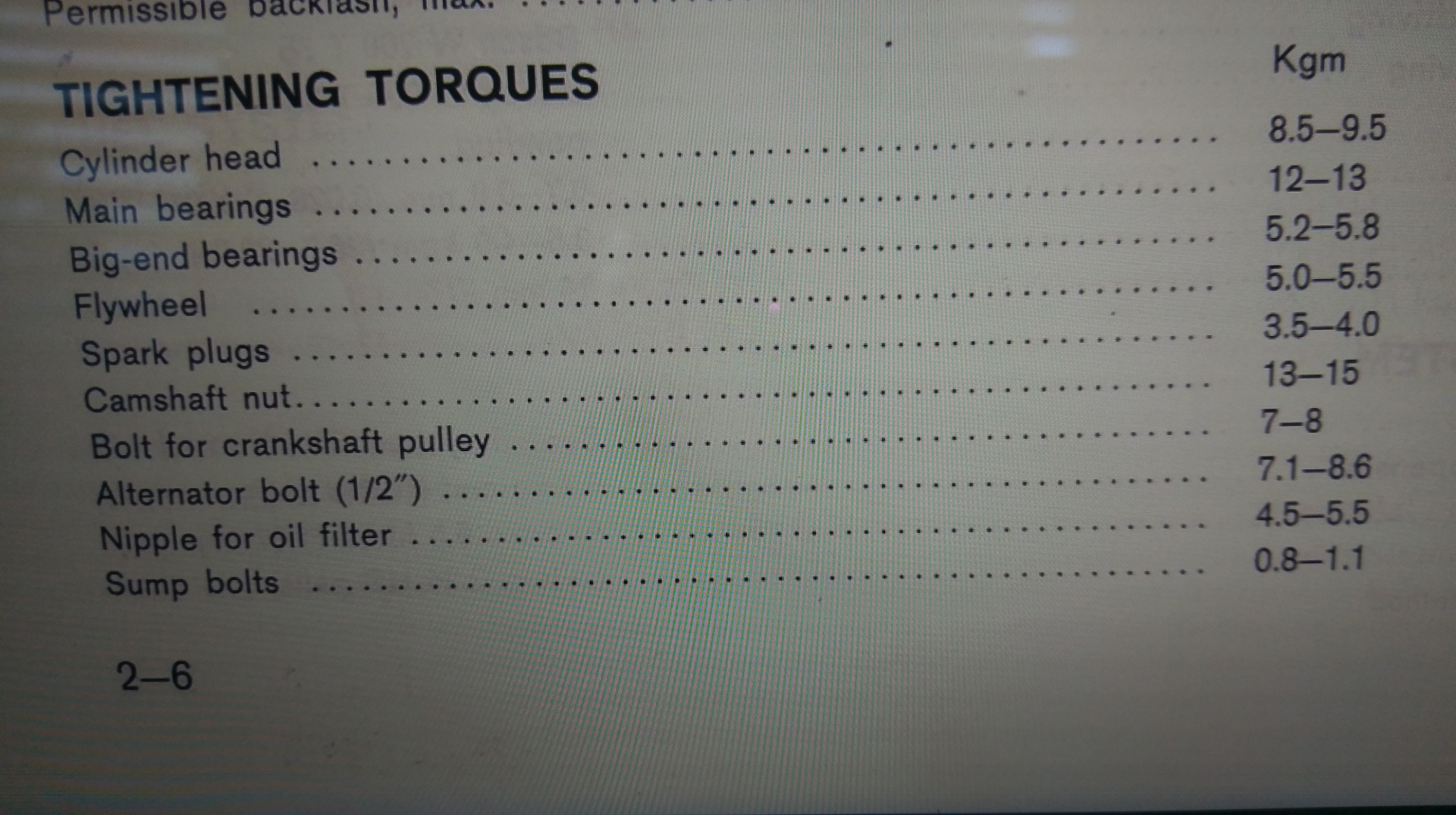
I torqued the main cap bolts. I had to take another pic from the manual.
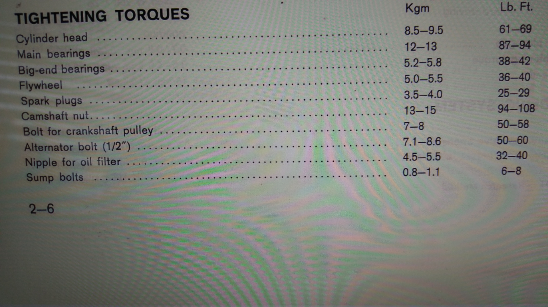
Just to lazy to convert Kgm. Not sure why there would be a range for these values so I went for the high side after first doing them all to fifty pounds. Of course remembering to oil the threads and under the heads of the bolts.
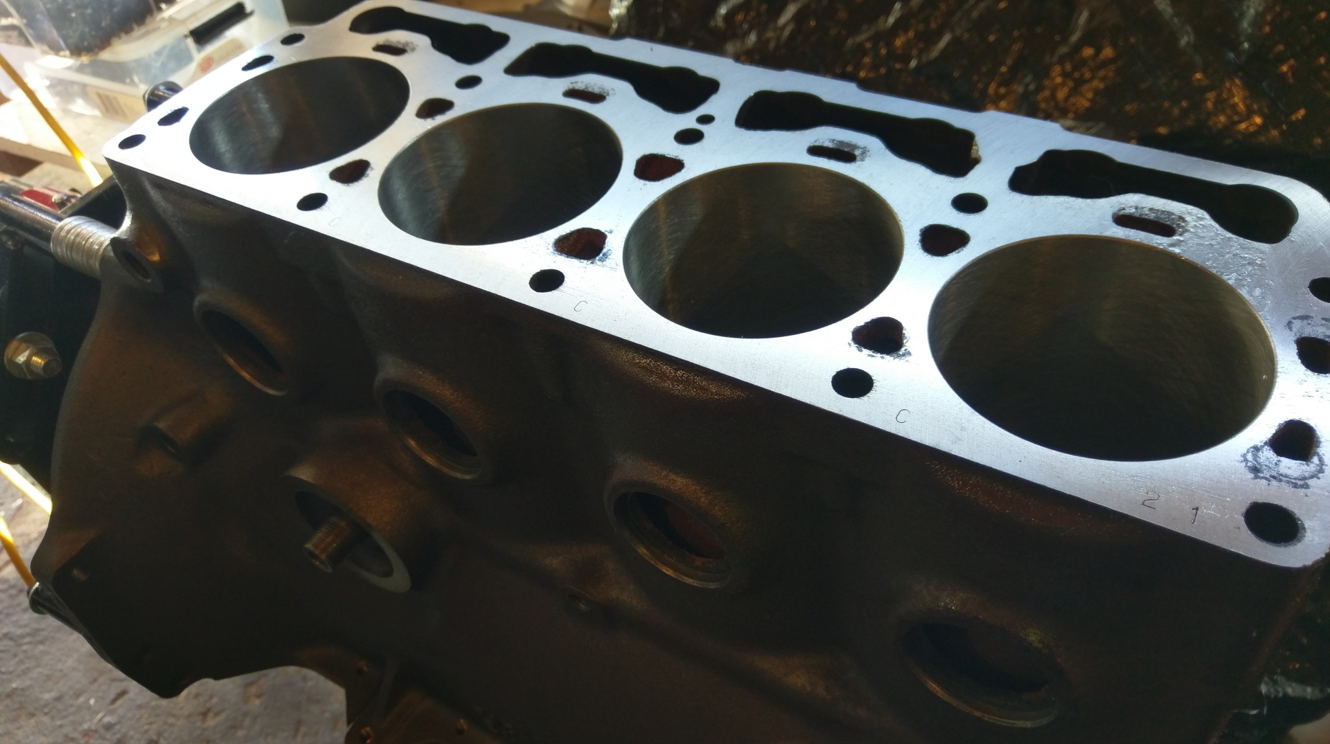
With the mains done, flipped the engine over in the stand ready for the pistons to go in.
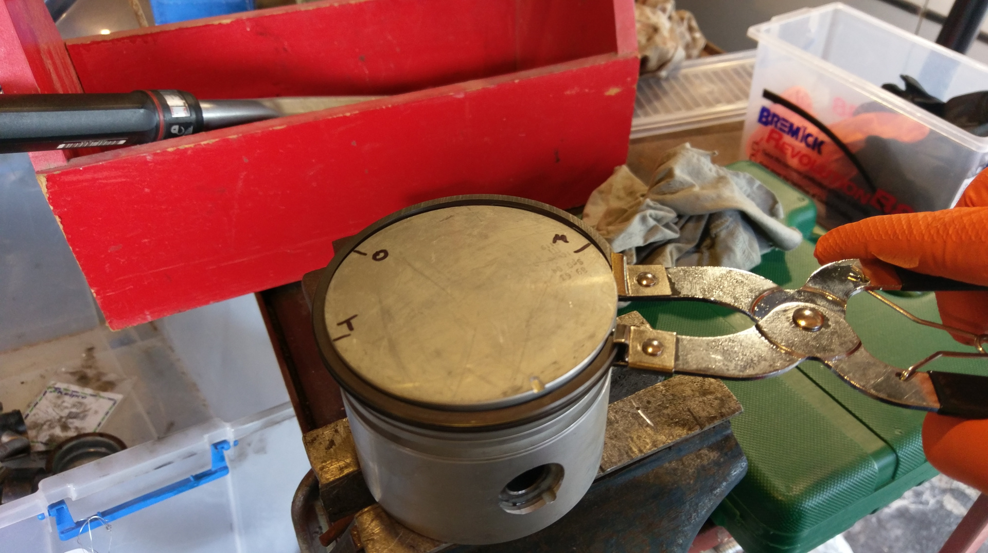
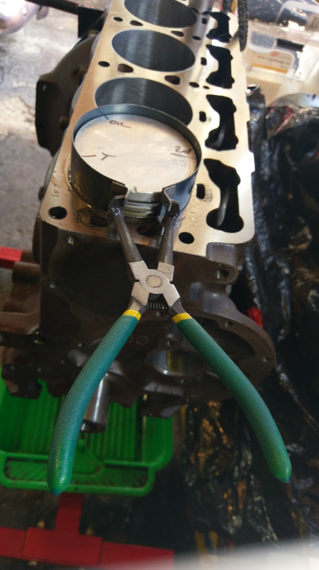
The pistons came with the rings installed, so off they come with the eBay ring expander pliers. So much easier than using thumbs and keeps the blood on the inside.
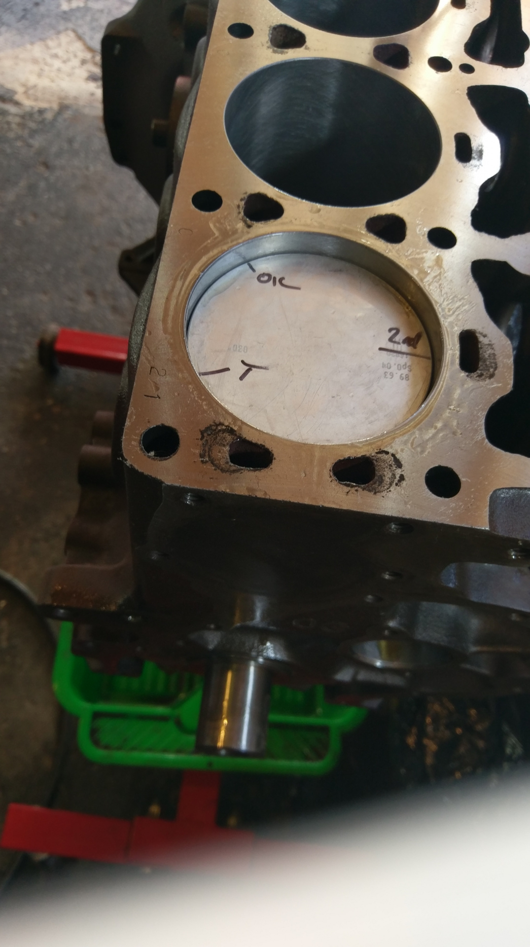
Popping a ring in the bore and pushing it square with a piston.
Measuring the end gap for each kings of ring with feeler gauges.
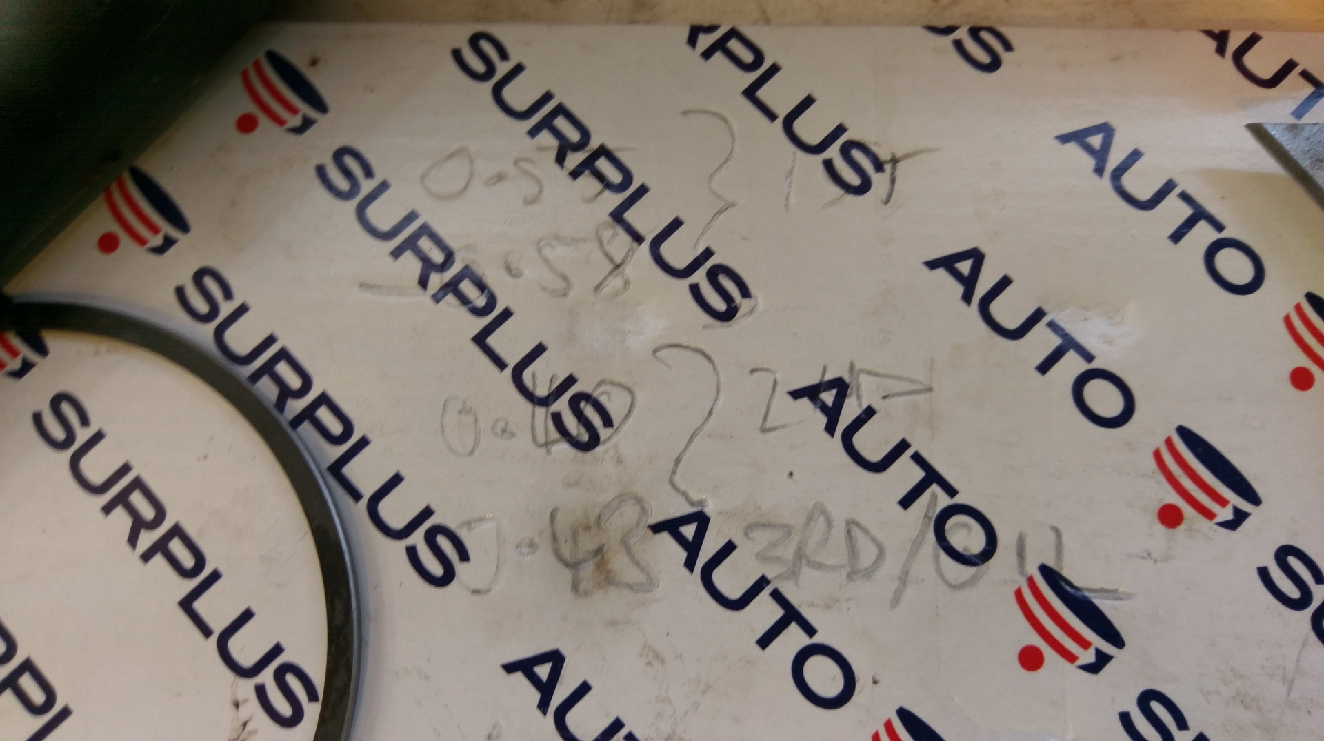
My measurements. Kinda hard to see.
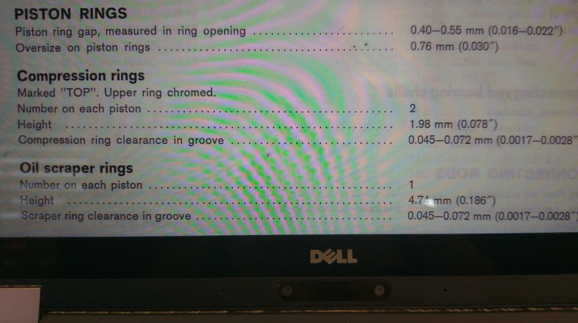
But came out pretty close to the spec. Little on the high side for the top ring at nearly .58mm.
Will have to live with it tho.
The Manual is a bit vague when it comes to positioning the piston rings, just saying to put them apart.
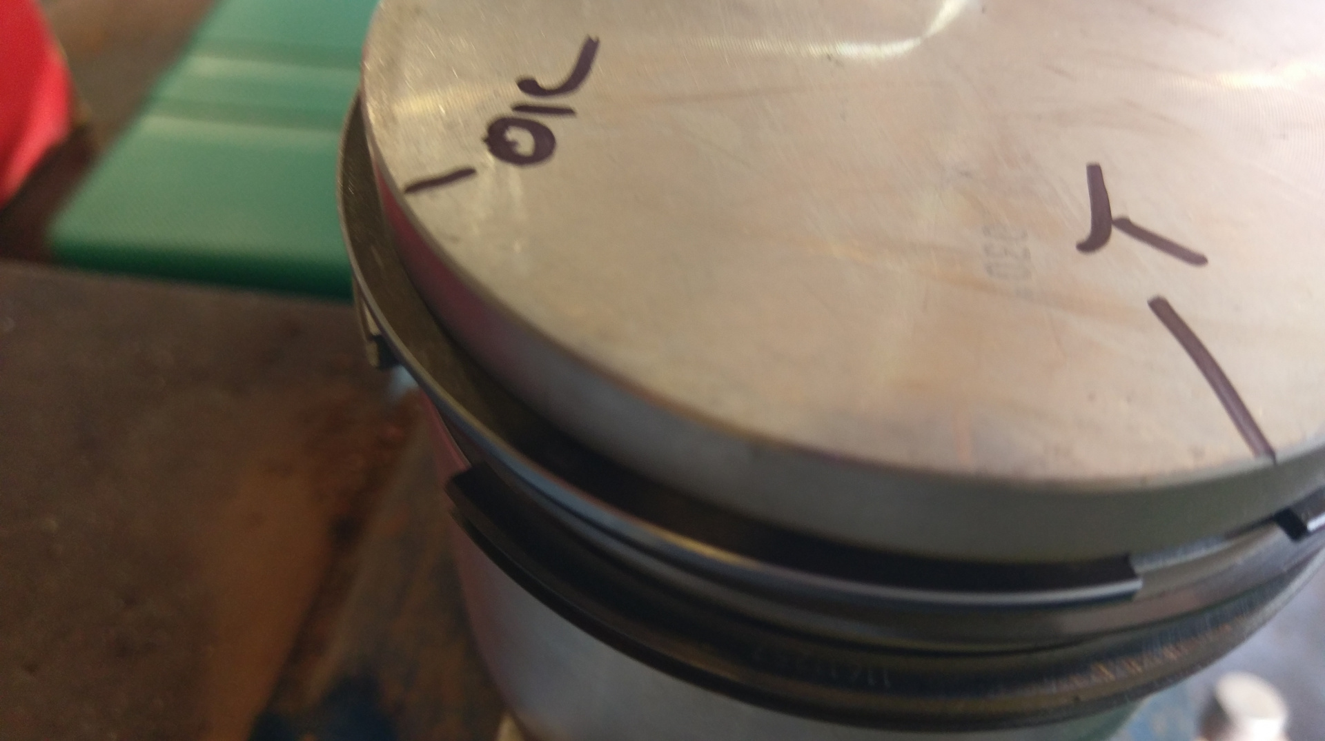
I ended up going with the top ring far from the plug, offset a bit from the oil ring. If the front notch in the piston is at the six o'clock piston, the top ring is about eight and the oil ring is between ten and eleven.
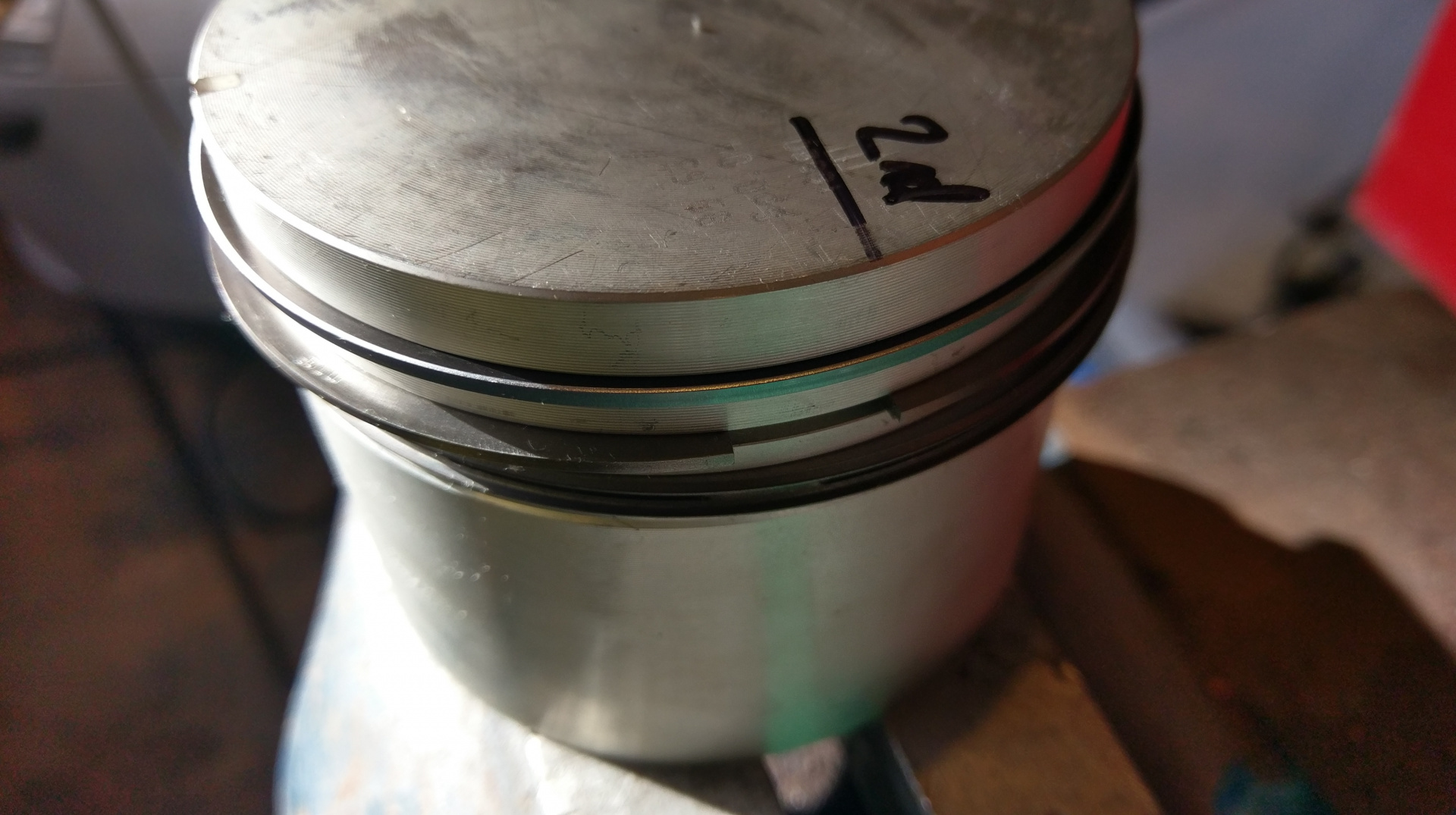
With the second ring at three.
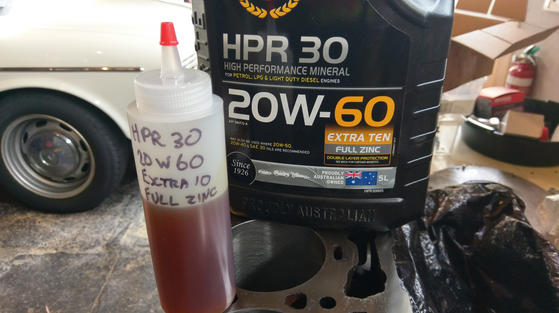
For lubricating the piston and rings I filled a squeeze bottle with my chosen engine oil.
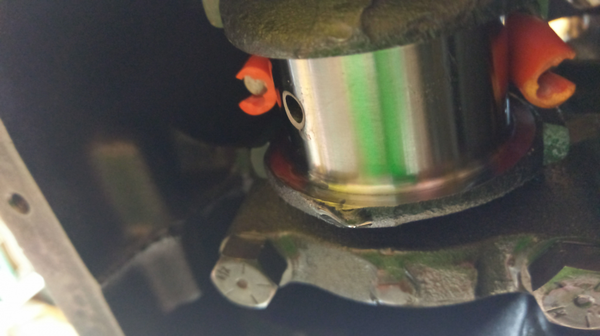
Do you think I could find the nice silicone tube I was going to use on the rod studs to protect the crank journals... I had to improvise with the sheath off some 15A cable. Really important to not let the rod threads ding up the crank.
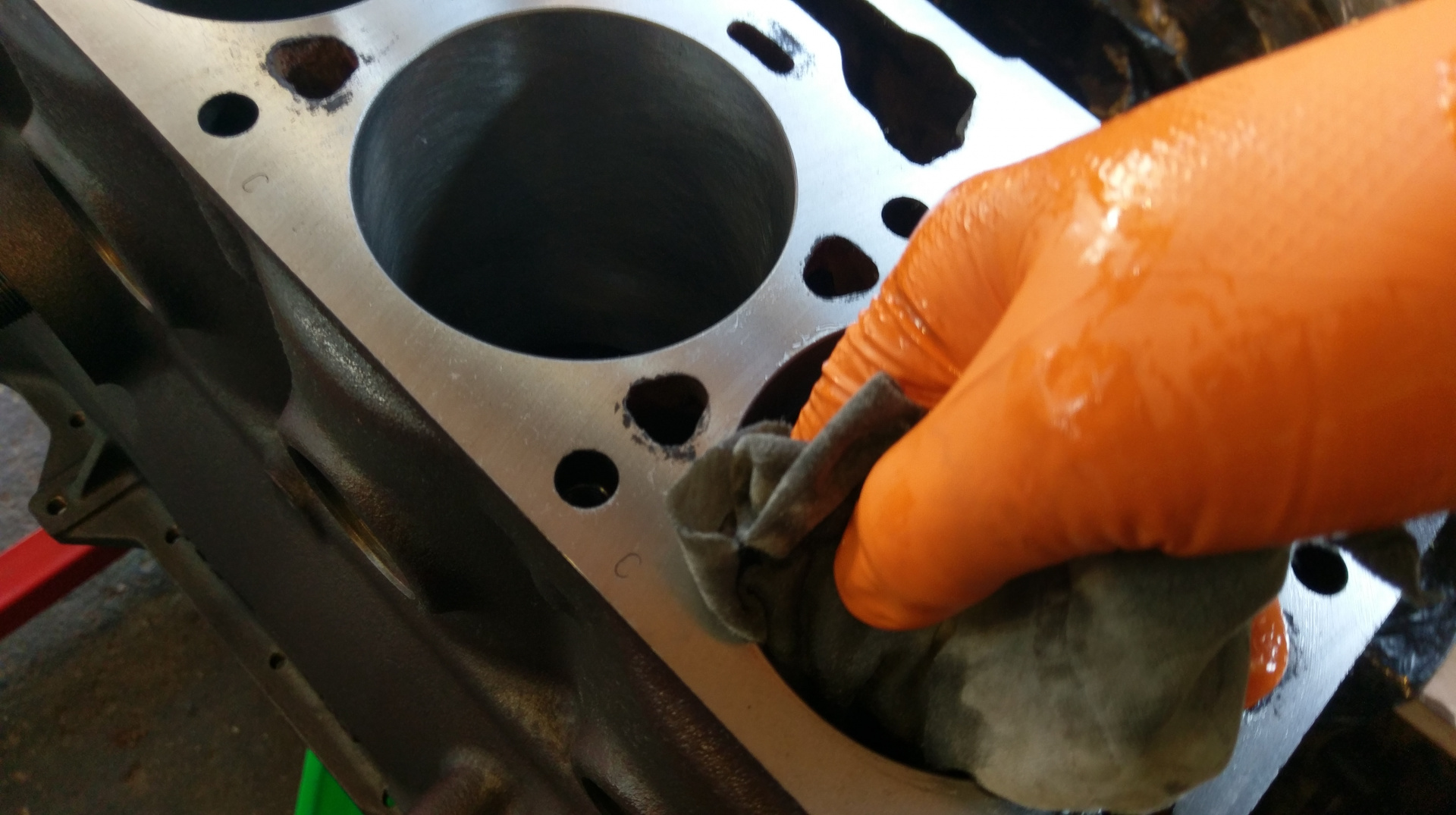
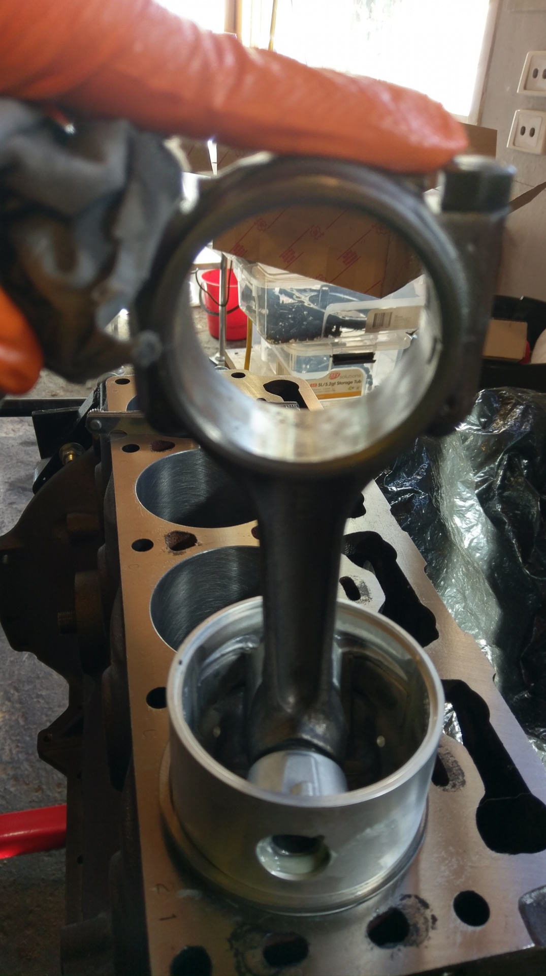
After wiping the cylinders clean, I used an engine oil soaked rag to apply a coating. This HPR30 is some thick sticky stuff. I wiped clean the piston and rod and hit it with some compressed air. I wiped a coating of engine oil into the piston and squirted oil all over the rings, jiggling and spinning till the rings and grooves were fully coated.
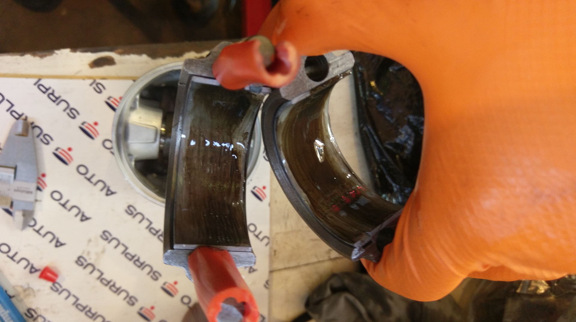
Wiping the shells with a clean rag and acetone then treating the big ends with some assembly lube and engine oil.
I rotated the crank till number one was at the bottom, wiped the journal clean with acetone and slid the piston in. You can see the liberal coating of oil. I lined up the ring ends as the move with handling.
The budget eBay ring compressor worked really well, making it effortless to get the rings into the bore.
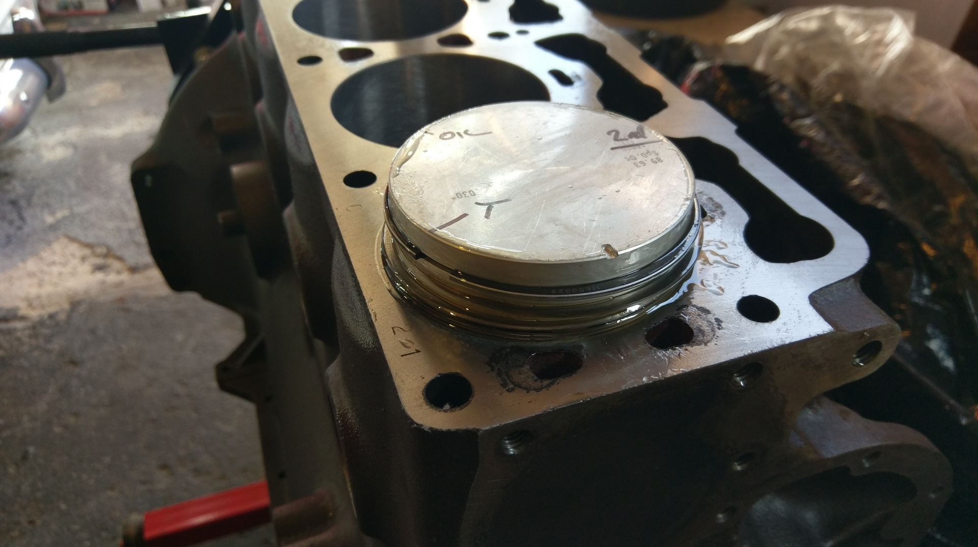
It's in, hooray.
Keeping an eye on the descending rod while sliding it home, seating or with a light tap with the handle of my plastic hammer. Then installing the big end cap with a tap of the plastic hammer. I made sure to line up the cap so the bearing tangs are on the same side.
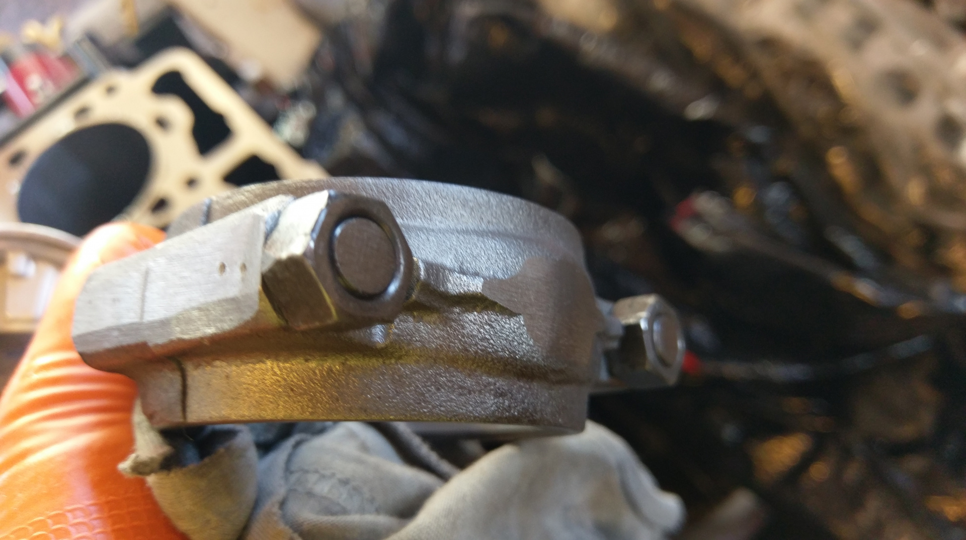
when installing the nuts I made sure to put them in with the linishing marks outward. As mentioned in an earlier post, the weights must have been way off. To match rod weights this one got quite a going over on the linisher. The stud ends and cap end and sides of the big end ground away quite a bit.
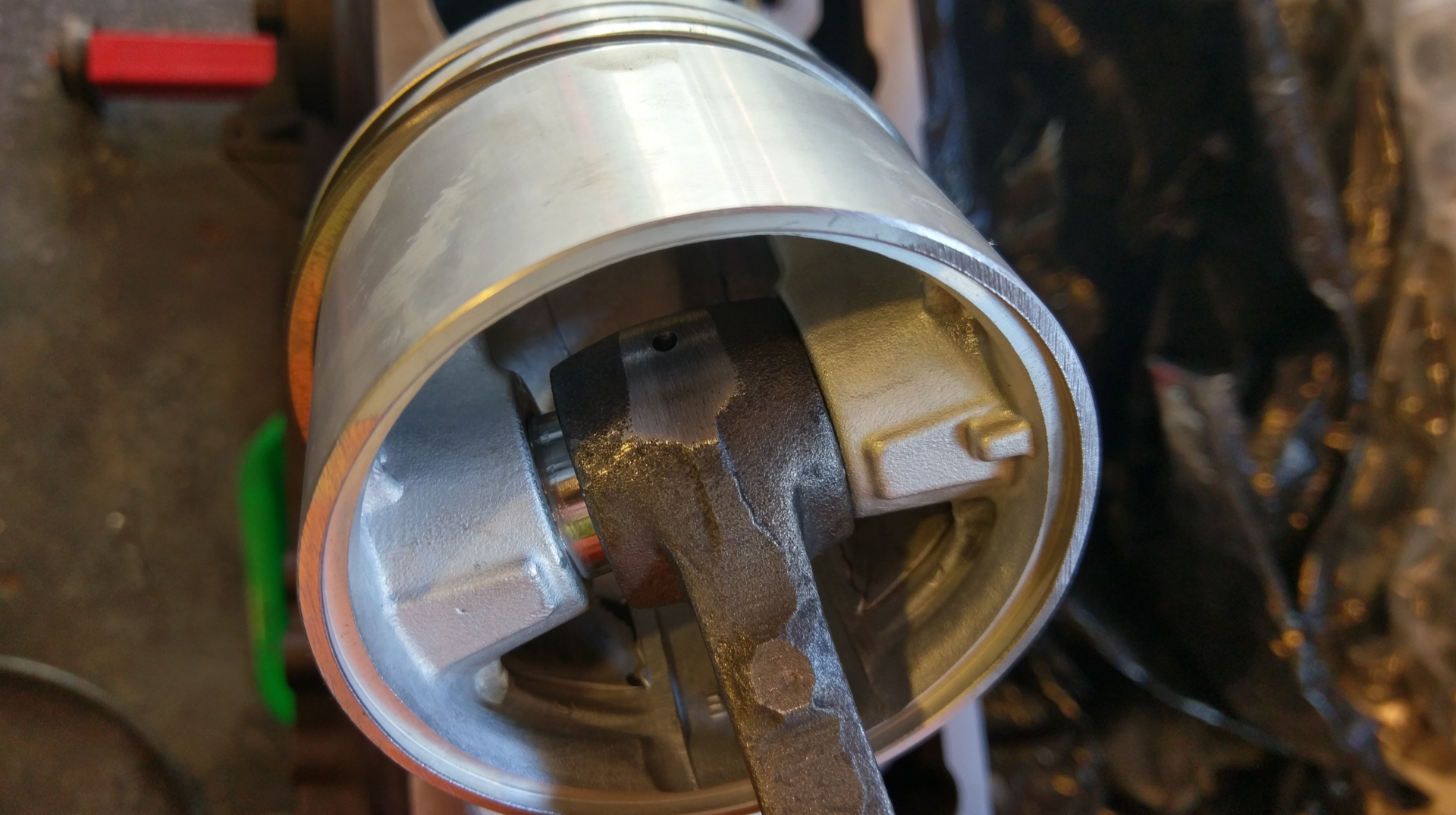
Here you can see grinding in the sides of the piston skirt as well as the little end.
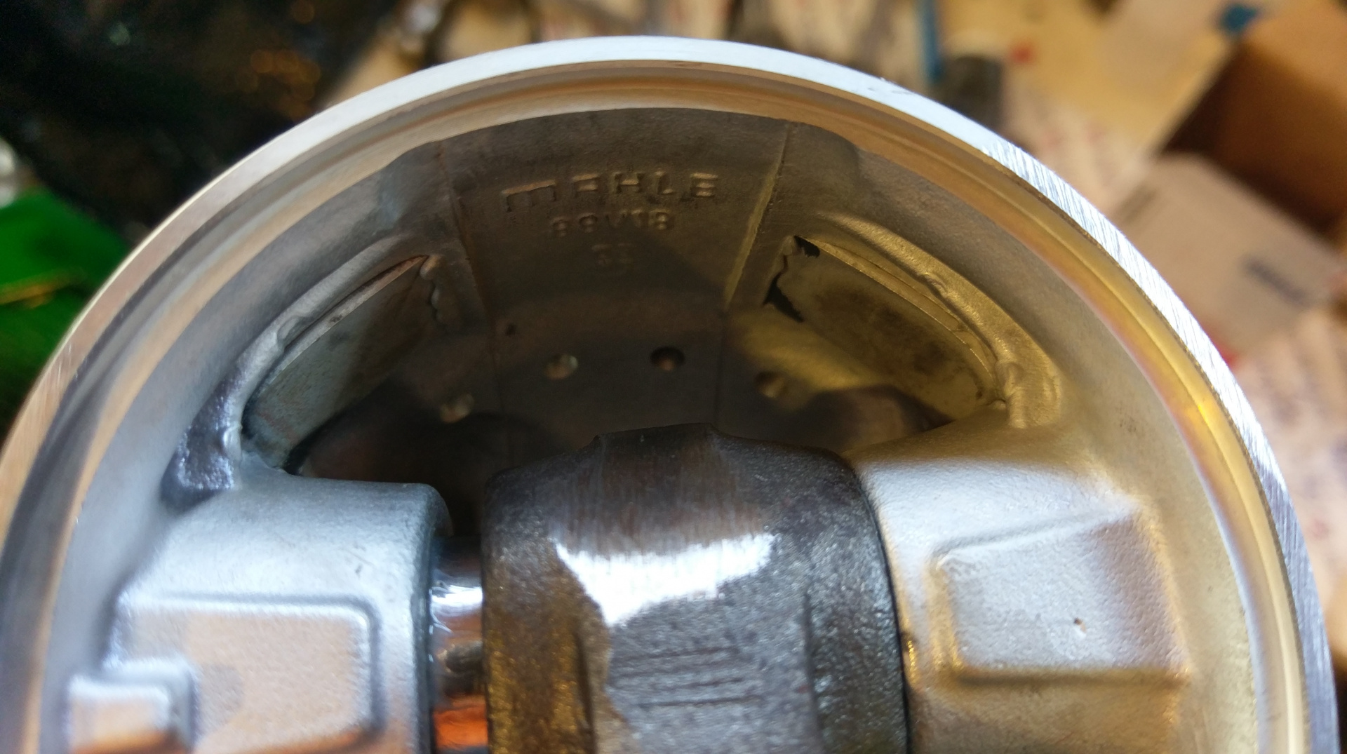
In fact, right over the top of the little end. I also noticed that these pistons have some steel(?) reinforcements cast in. I wonder if this is for strength or expansion characteristics.
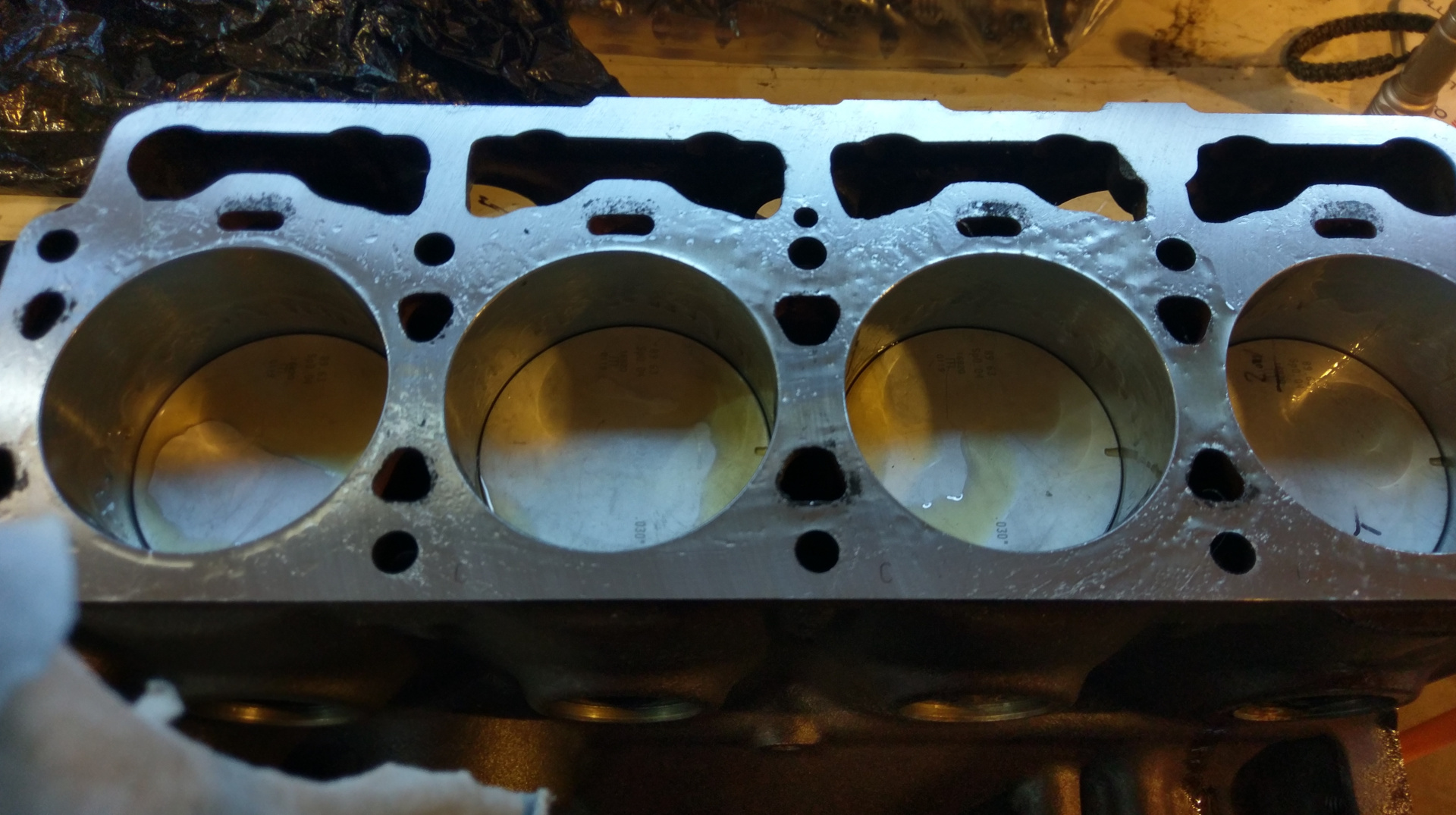
Rinse and repeat for the rest.
All tucked in till next time.
They're called hypereutectic pistons from memory, standard fitment on B21 and later engines.
Great detail, and progress.
- Edited
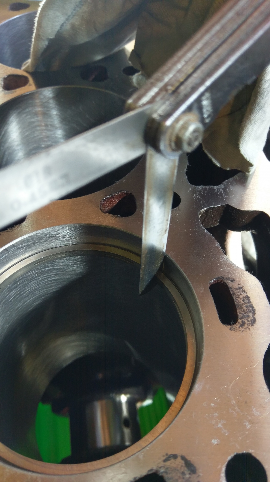
So, I also did some measuring of deck height...
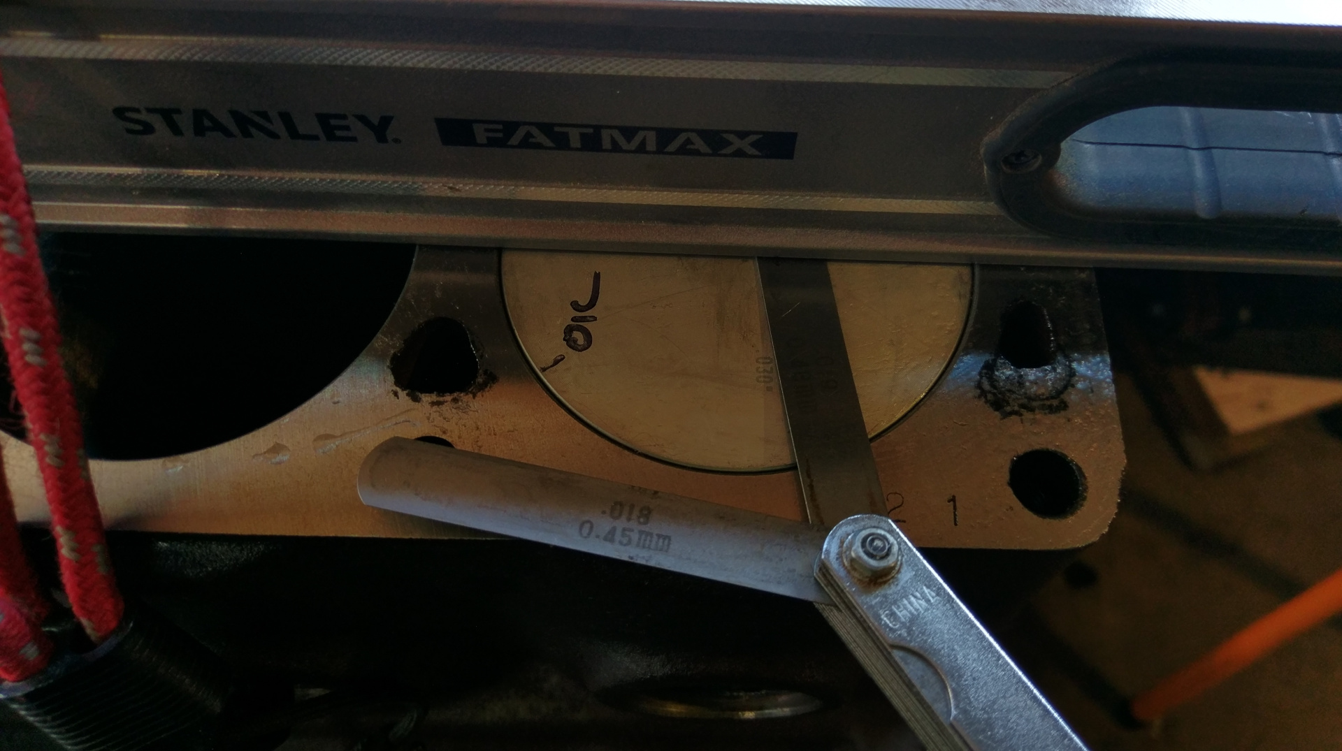
I ran a stone over my spirit level to make sure it had no raised burrs. It is probably the flattest thing I have. I then held it in place with an ocky strap.
Using feeler gauges with the piston as close to top as possible, I started loose and increased the size until the level moved when I slid the feeler underneath. I then tested with the largest that fitted while tuning the crank to be sure I got a measurement with the piston right at the top, it got tight but didn't move the level. One size up and repeat, this time the level lifted as the piston reached top.
So, the piston comes to 0.45mm below deck. That is rather terrible!
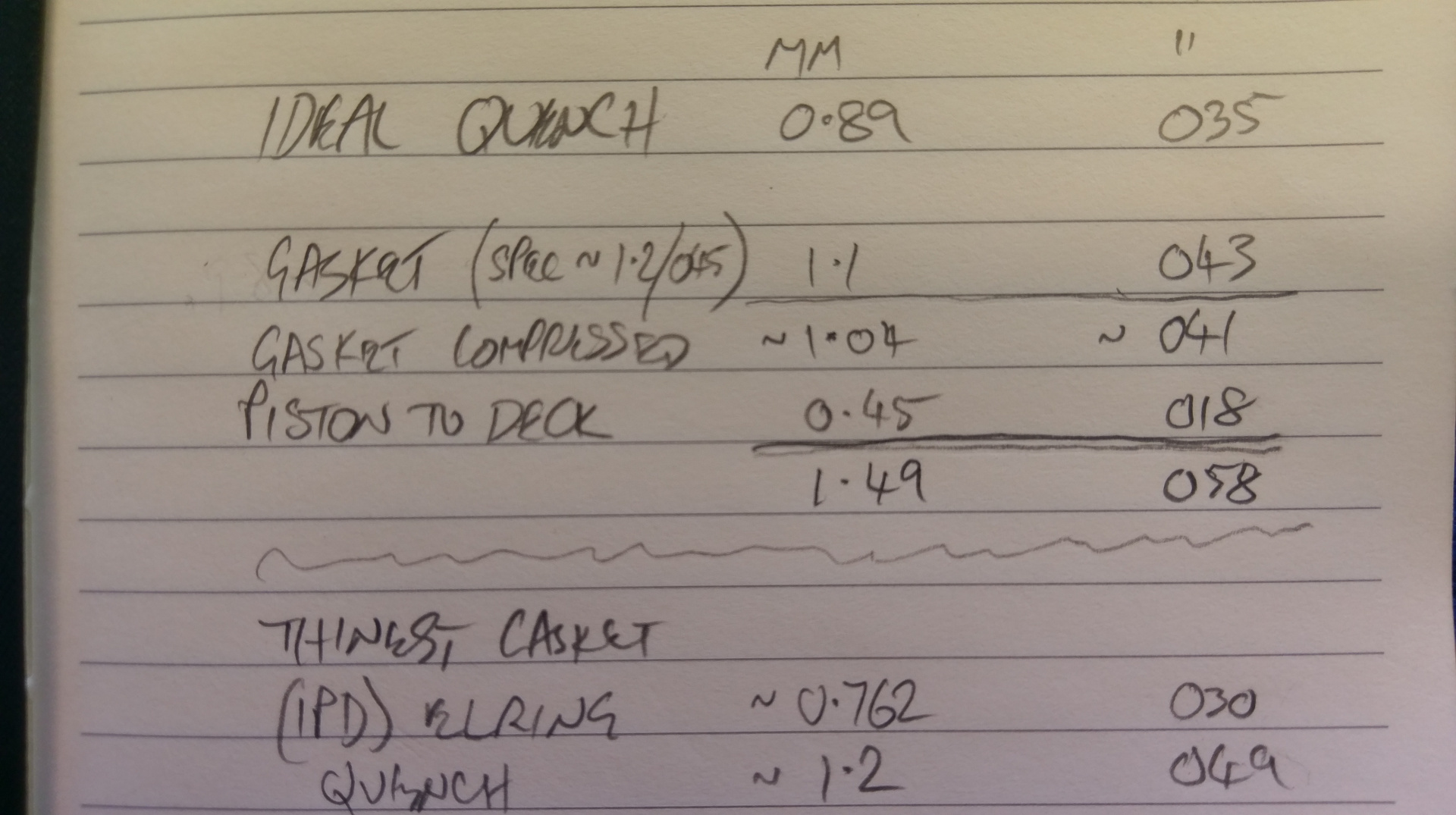
With a bit of working out and some guess work. The head gasket is about 1.1mm and will probably crush to about 1. With the pistons 0.45mm in the hole gives me a quench of about 1.49mm. Even using the thinnest available gasket isn't enough. A custom gasket would have to be super thin. If I work on the best compromise, and in the future use cometic MLS 90mm and 045 (1.14mm) thick (expensive tho at $175 to $200+ for something that is not supposed to be re-used) if I knock 0.7 mm off the block, my current gasket will give me 030, and the cometic 036 (0.91mm). This would be about perfect. The internal debate I am having is to go this way out order 0.85mm (033) gasket(s) from cvi. The cometic can be had at 90mm/030 too. This would leave more for future machining, but I still need a new gasket right away.
AFAIK, the MLS gaskets don't really crush from the spec and the traditional style only crush about 010 to 030. [edit: I mean 001 to 003 thou]
Ether way would work. Any thoughts about long term gasket availability?
I know, I know, I should have just paid the shop to do the assembly and measured. I did call and it will be about $130 to machine and clean, as well as not too much work to re-do at this point.
My research agrees with @Vee_Que to aim for about 035 quench, certainly under 040 with the only real risk of going lower is when the whole thing wares out, and the pistons can rock more and the bearings have more clearance, that the pistons may kiss the head under high revs. The 030 quench scenario above would be ok, as a new gasket would go on before much wear.
Any thoughts?
Thanks,
-Todd