• RWD
  • 122s engine rebuild plus more - UPDATED 16 Sept - CC'ing the head

With a gasket thickness of 0.95mm (037) and allowing for a few thou crush, I think I might be best off to zero the deck height and go with that.

hmm...

Zero deck sounds safe to me, the reduction in pinging risk is worth it.

Thanks @Vee_Que. After all of the measuring I was still leaving a variable I wasn't satisfied with, gasket crush.

I made some solder blobs and cut extra holes in a head gasket. I had to experiment with various sizes of solder blob, I had to go surprisingly small to get a suitable size crushed diameter for the thickness I was aiming for. The only hole punch I could find was 3mm, so I used it to nibble out some fairly ugly holes at four spots around the gasket.

pretty happy with the work done on the head.

The gasket in place with the four lead blobs of the extra holes.

Then I torqued it down to spec, had lunch and removed. The measured I got was 0.91mm for the three that are in the main area of the head and 0.93mm for the one that is off to the side in the lifted area. Hardly any gasket crush at all as it started at 0.95mm.

0.91mm is real close to 035.

I took my earlier deck height readings, did some (crazy) averaging and landed back at 0.45mm (018)

After all this I am super confident that machining 018 off will get me exactly where it should be while erring on the safe side by a few thou.

The block is on it's way back to the machine shop.

Sorry for the long and drawn out part of the build. I am sure things will speed up. Unlike cam and head and nearly everything else, deck and quench can only be fixed now.

Thanks for all of the advice.

-Todd

9 days later

I have my freshly decked block back from the machine shop. $140 for deck and clean. For me it is worth paying the extra sixty bucks to not have to spend a day of available time cleaning the block.

Hopefully I have time to get stuck into it on the weekend.

18 days later

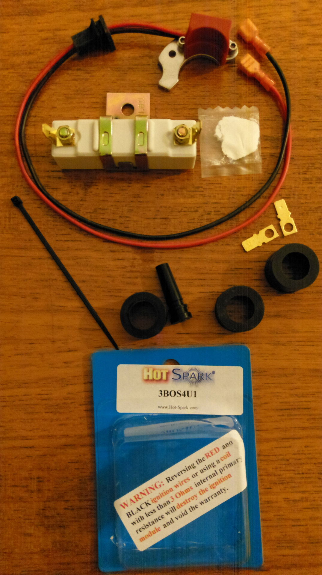
This gizmo arrived in the mail a while ago...

I was feeling a bit down and needed a quick win. So I got stuck into getting rid of points. I wish I had one of these when I had my old hilux years ago.

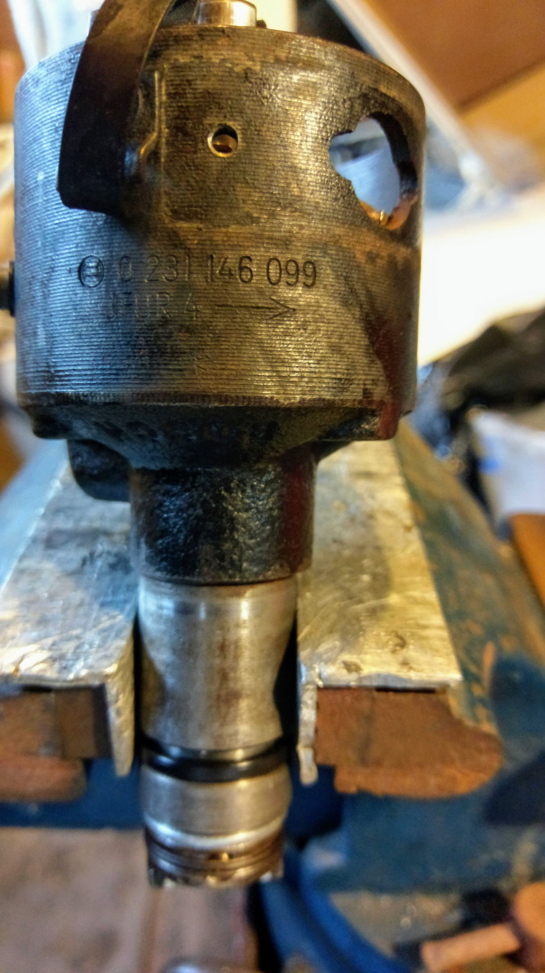
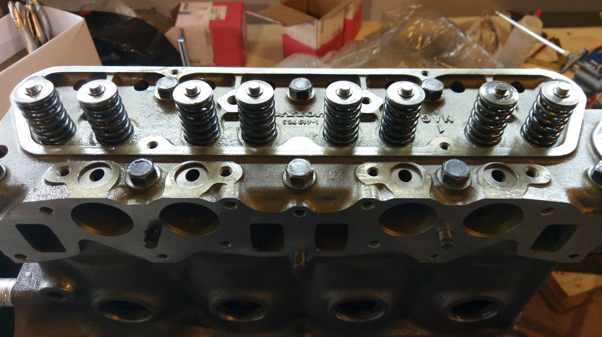
So the first thing was to strip it down. (although I think this pic was after cleaning, but I wanted a record of the part number.)

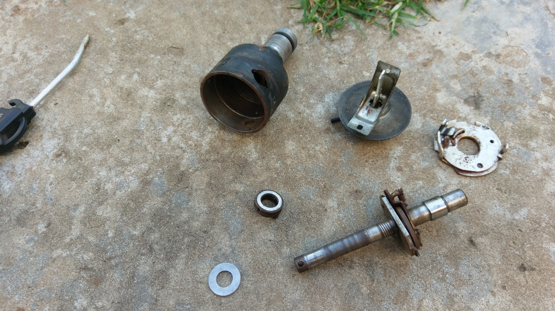
I stripped and cleaned all of the parts. The first thing I noticed was that there was heaps of end-float (I didn't measure but about 1.2mm) in the main shaft. There is a top shim which is quite thin that goes underneath the main plate, whatever it is called. There was also a shim between the bottom of the housing and the offset drive dog. I modified a washer by drilling it out the hole and lapping both sides to ensure it is flat and does not wear out the drive dog. I then broke the existing shim. It was just a fiber washer. So I had to make another spacer out of a thicker washer.

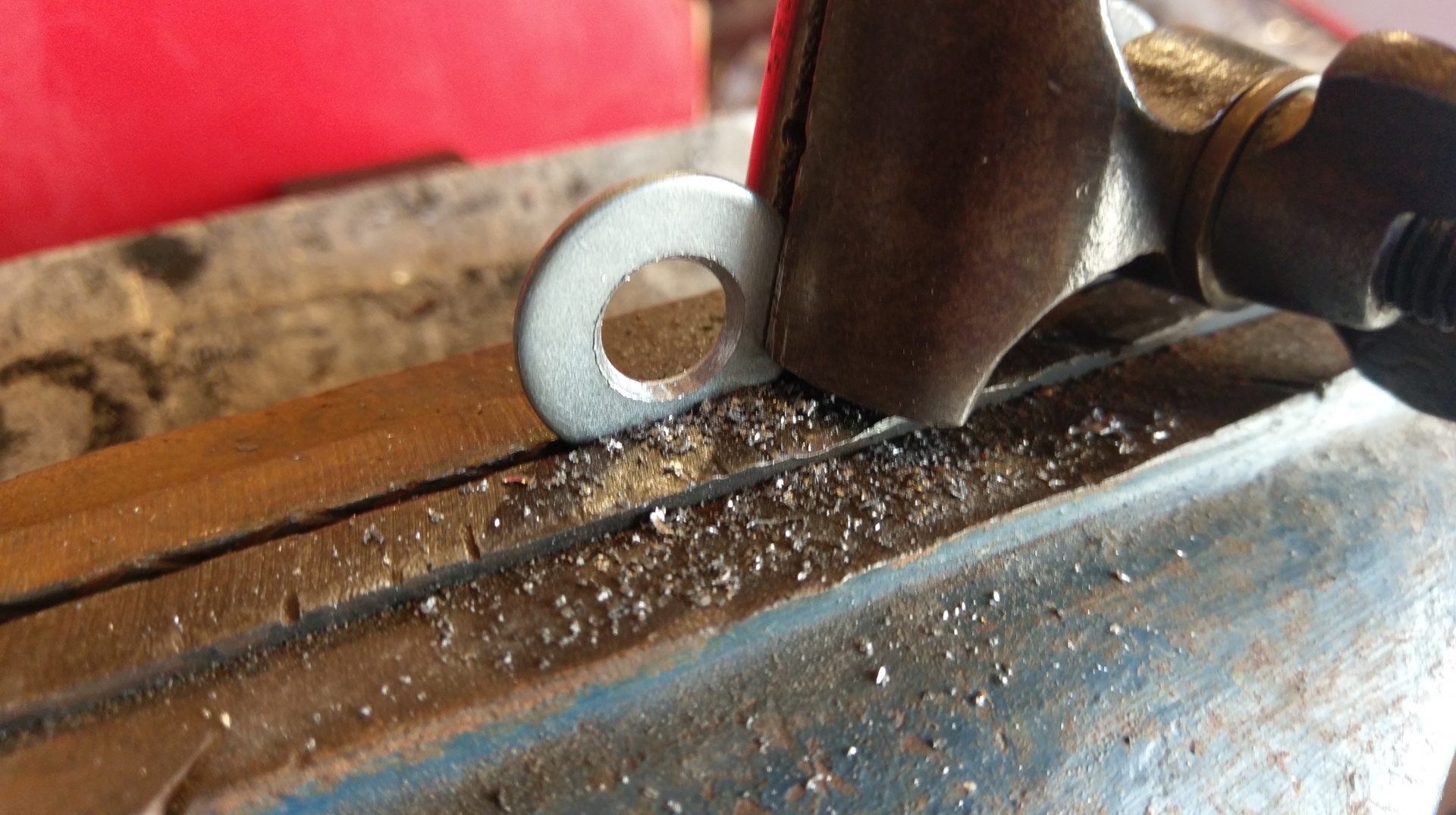
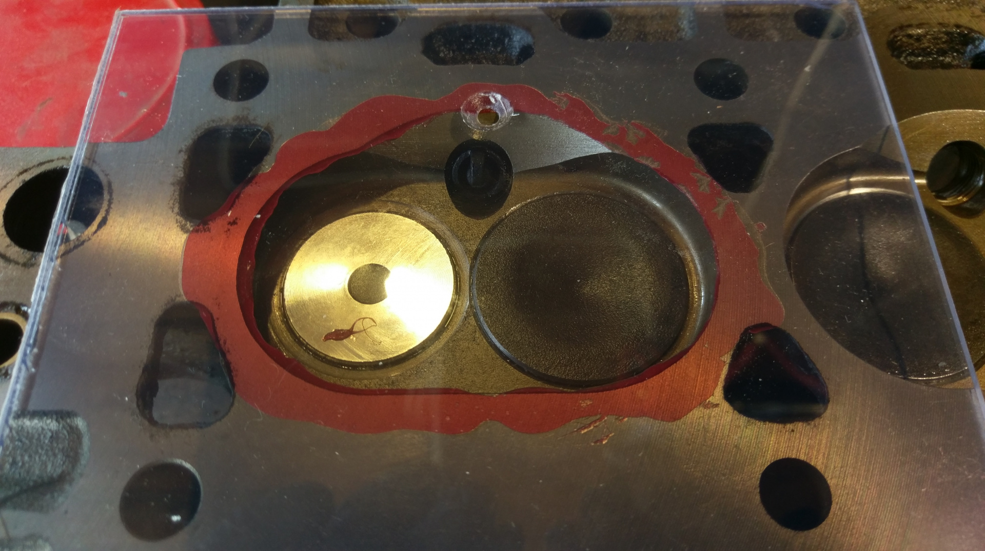
The first pic is the spacer, drive dog, pin and spring re-assembled. The spring going around the drive dog gave me the impression that the pin would be a slip fit, but it needed to be driven out rather firmly with a punch. with the main shaft back in with the new shim/spacer washer there is about 001" end-float. Hopefully that is enough. I noticed on the housing there is an oil hole into the top bush. I guess it is supposed to be serviced by squirting some oil in the hole, and then it dribbles out everywhere. At the top of the bottom part of the shaft there is a spiral. This is there to direct the new oil downwards. I spun the shaft with an allen key in the drill with the hole upwards and watched it sort of suck the oil in.

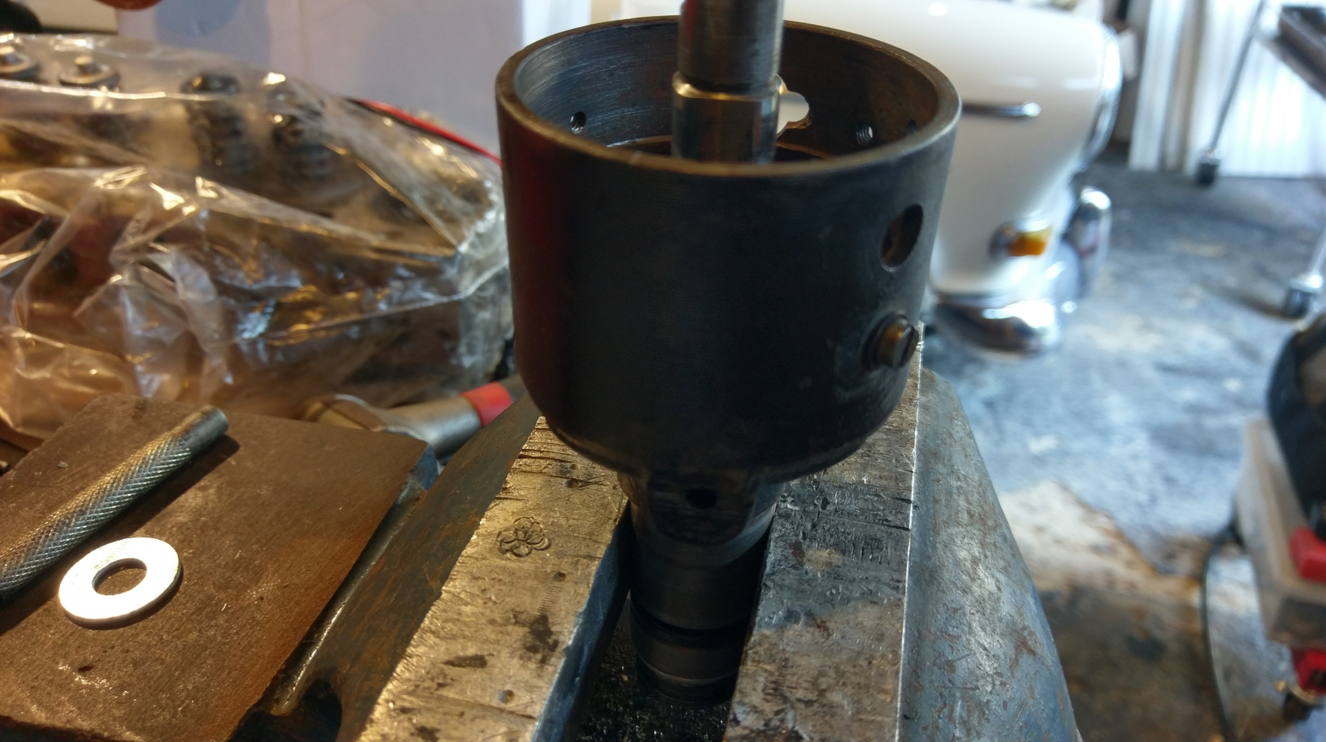
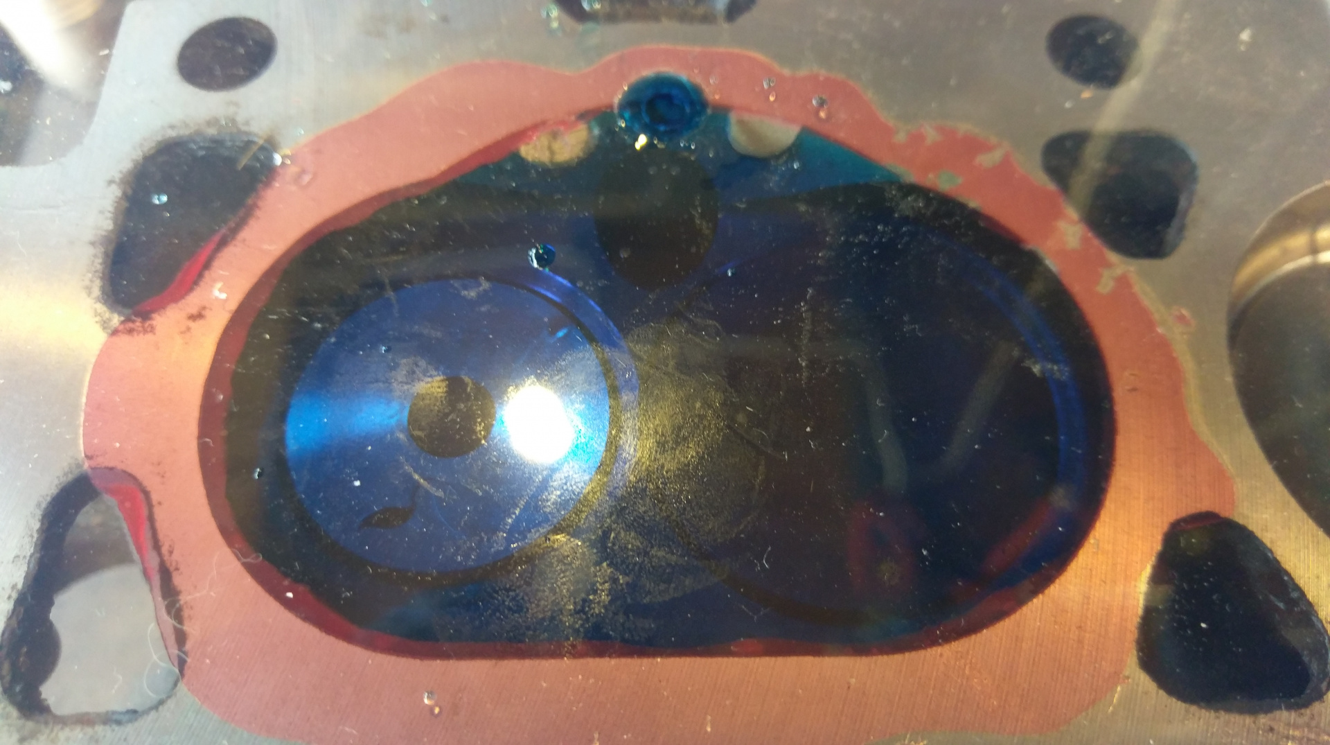
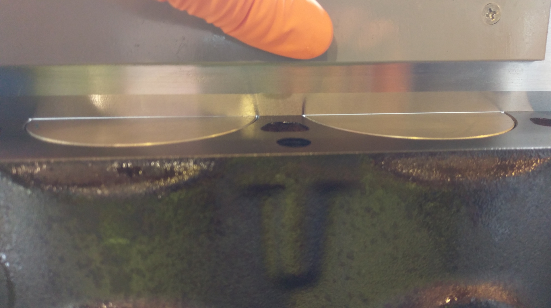
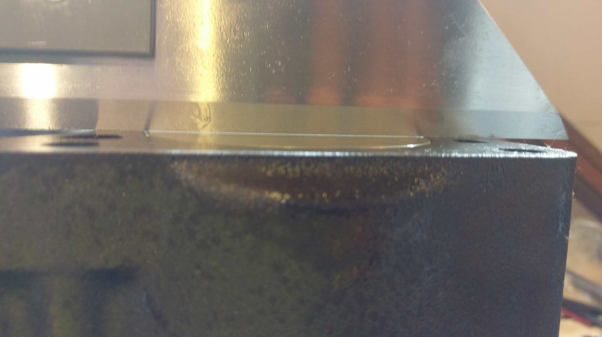
This pic is too dark, but the hole toward the bottom of the housing can be seen.

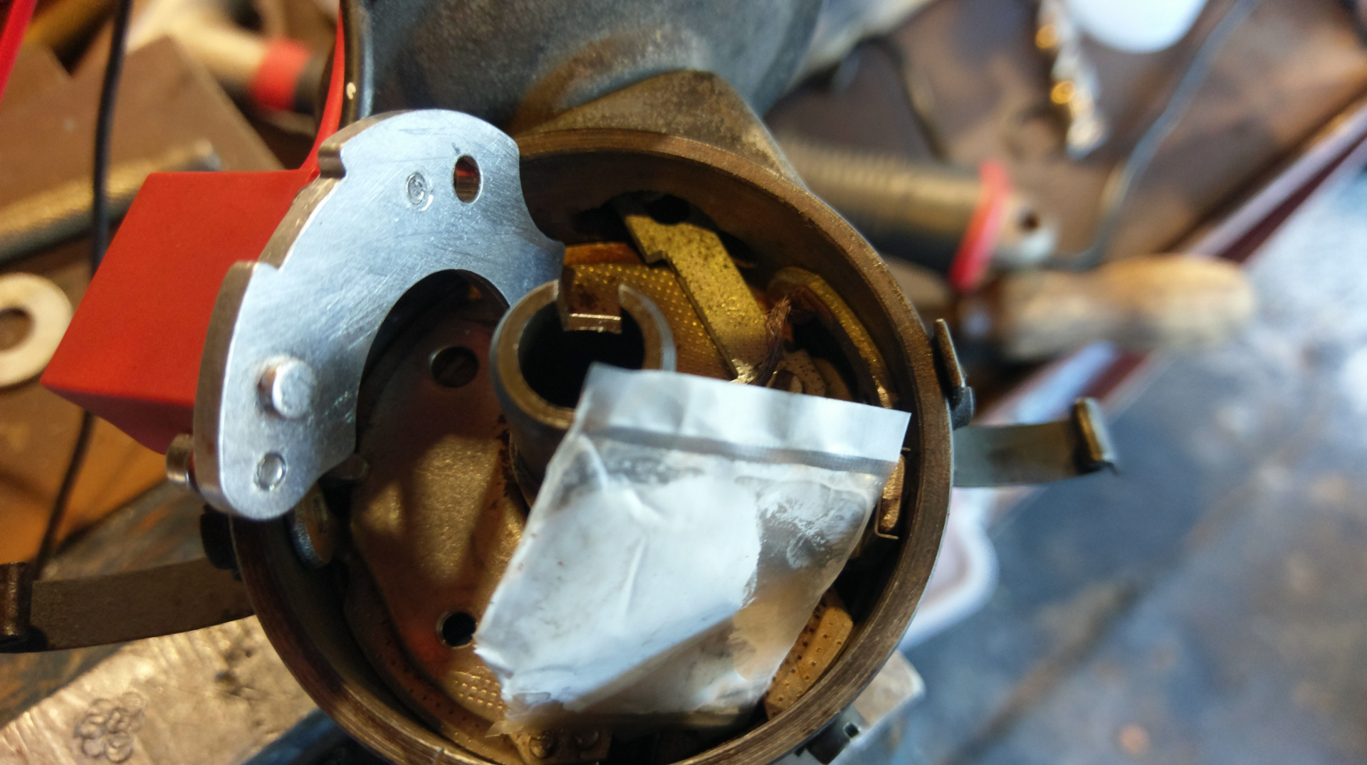
I had to stone the bottom of the unit flat where the thread was raised by tapping. I also had to us a punch to flatten the mounting hole on the vac advance (well much stupider, if that is a word, vac retard) plate as it was raised by many years of having the points over-tightened. Then I fitted it with the thermal paste.

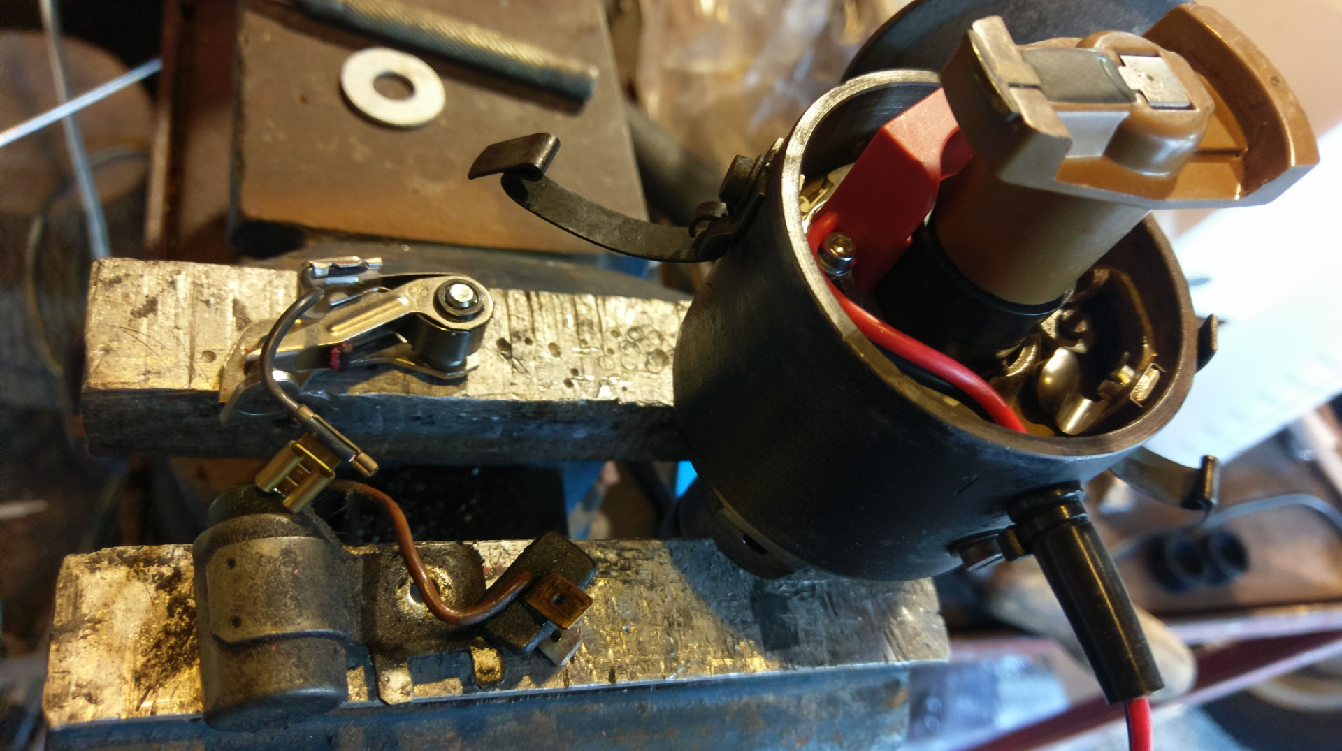
There we go, out with the old and in with the new. I re-fitted the dizzy and it still didn't work. I had to swap the magnet ring for a shorter one. Unfortunately the shorter one was looser, I cleaned it and the lobes with acetone and applied a small amount of gasket silicone and fitted it.

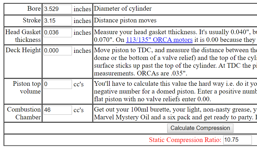
Timing was just as easy as points and on the old smokey rattly engine it seems slightly more stable and a bit easier to start. I did install the ballast resistor between the module and +ve ignition as recommended if charge voltage is a bit too high. Currently the charge is a bit over 14V but you never now when the regulator may crap out or whatever.

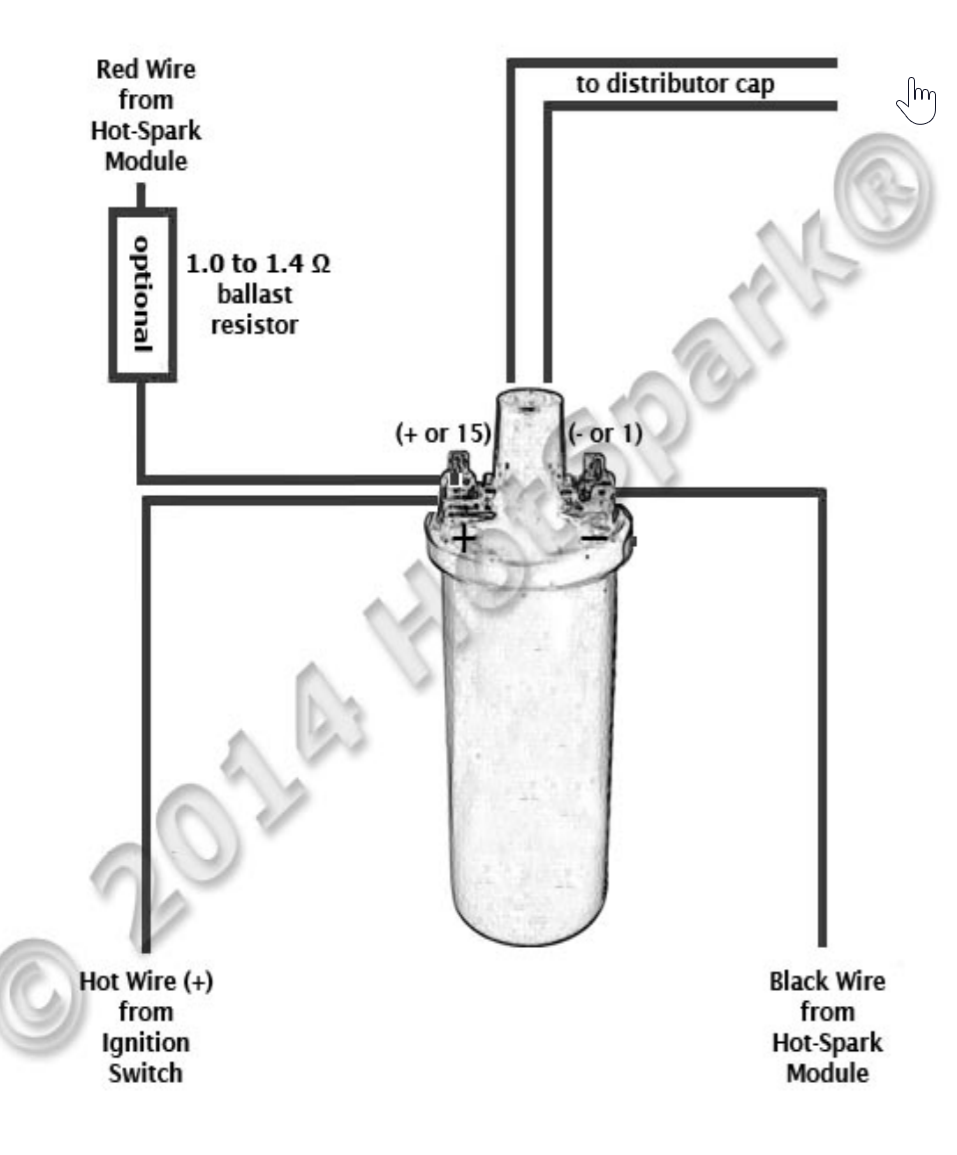
This is a snippet of the installation instructions that can be found on the Hot Spark website http://www.hot-spark.com

I chose this module over the slightly cheaper eBay units as it had a website with install info etc. I am not specifically endorsing this product and I have only been for a brief trip around the block with the poorly running engine and it seems to do exactly what it says on the tin.

-Todd

Good on you for writing up a very comprehensive build post.

While I've never don't this work before and I don't understand i can see if I was doing the work it would make it much easier for me.

Please keep posting details,I'm loving it.

Lots of pics too please.

Well done and good luck.Les

With a gratuitous picture of a nice clean crank I re-assembled the crank and pistons into the newly machined block.

Next on to CC the head. I cut a piece of perspex, and countersunk a hole. I have a 100ml measuring cylinder full of blue, a syringe with silicon tube and a funnel (a unused adhesive cartridge nozzle)

A bit of grease around the combustion chamber and fit the plate.

Fill it with blue and measure the difference.

That way left bubbles, so I did the rest from a different direction, then wend back and did the first again.

They all came out as close as I can measure to 54, which, inverted is actually 46cc each.

And then to re-measure the new deck height. on the left is #3 and #2 on the right.

#1

and #2

As you can see, I invested in a "real" straight edge. This and feeler gauges seems to be a far more accurate and consistent way of measuring compared to the dial gauge. Ultimately it came out to be between a little less than .001" and .0025". The pistons aren't completely flat. Also this time I assembled with oil only and no assembly lube. This made it much easier to turn the crank and could have added a little to the variations.

Regardless the end result came out as;

Which I am pretty happy with, and if re-calculated with .002" deck height it comes to 10.69:1. I expect I will need tune for premium, but only testing will tell.

I used the calculator from https://www.rbracing-rsr.com/compstaticcalc.html. It was the first hit when I searched.

This really is as close as I could have hoped for to get a decent quench.

Thanks for looking.

-Todd

Depends on which cam you decide to use and it's valve timing = dynamic compression ratio

  • todd replied to this.
    ramrod

    Depends on which cam you decide to use and it's valve timing = dynamic compression ratio

    Hi, yeah, fair comment @ramrod, I agree there are a lot more factors than just static compression.

    5 days later

    http://www.bigboyzheadporting.com/TwinCamComp.htm

    This link will give a more precise calculation for static taking into account ring position and piston diameter.

    Dynamic compression table worked for me, using known cam intake ABDC angle.

    Intended for HD motorcycles, have used many times.

    Methylated spirits with food dye for measuring cylinder head CCs works for me.