- Edited
OPTION 1 - Without OE Switch (using front Foglight switch inside the vehicle - disables fog lights).
Only applicable with front OE fog lights (not day running lights)
Modified Wiring
A NEW control relay is added (hand drawn) that is activated when the fog light switch is on, and supplies 12v from high beam to the NEW Aux light relay (2/64). NOTE the breaks in the OE circuit.

Hardware
- 2 x relays
- Spade lugs
- hookup wire (1mm2 and 3mm2)
- Disconnect both front fog lights.
- Remove LHS headlight
- Identify high beam circuit and splice a wire to supply the NEW "control" relay (+ shown as A1 see discussion below)
- Replace headlight
- Route LHS fog light loom light cabling into engine bay - see pic
- Cut down 2 thick spade lugs to 4mm wide
- Refer to revised circuit adding a control relay and pic of installation below).
- - Using spade lug, connect re-routed fog light cable (+ shown as 1 (fog)) to the NEW control relay terminal 86
- - Connect the high beam signal (spliced + shown as A1 (high beam)) to the NEW "control" relay terminal 30
(The control relay is energised by activating the fog light switch. This switches the high beam signal tapped from the high beam (A1) to terminal 87 of the control relay. This provides the (+) signal to energise the NEW AUX light relay (shown in the circuit by the OE relay 2/64) in the next step) - - Connect control relay NO contact (terminal 87) A1 in the hand drawn circuit to a NEW aux light relay coil (terminal 86)
- - Using spade lug, connect aux lighting plug (+) (the OE fused power supply for the AUX lights) to NEW aux light relay (terminal 30)
- - Ground both relays (terminal 85) to chassis (-)
- Connect lights using 3mm2 cable to NEW aux relay (terminal 87) and chassis ground point in engine bay.
- Put 15A fuse into position 2 of engine compartment fuse box.

OPTION 2 - With OE Switch (hacking another P2 switch to function as an AUX light switch).
You can either use a genuine AUX switch (no longer listed) or hack your own from another switch from any P2 car. Credit is due to some switch tear downs on a Russian forum, google translate and a discussion thread at swedespeed.com.
Any switch will do - they are all internally reconfigurable. Diodes (D1-D5) must be changed to match those in the following picture (i.e. only D4 and D5 present for the AUX function).
Disassembly of the switch and surface mount soldering is required (i.e. A fine tipped soldering iron, tweezers, solder wick and magnifying glass).

P2 switches have different diodes in place (D1-D5), LED's and labels.
- Window Lock (01111) : (orange LED)
- DSTC (11101)
- Rear AC (01011)
- Mirror (01001)
- Park Assist (11001) : (no LED)
- Interior Alarm (10011)
- AUX lights (00011)

I used a Park Assist switch (re-labelling the switch is still WIP).
(Note that a DSTC switch can also be added to later model without one).
In the diagram above (ignoring mark-ups):
- 54/8 (aux light plug labelled in the top photo) provides feed and control signal for a relay
- 3/60 is the internal Aux light console switch (repurposed).
- 2/64 is the lighting power relay
- 10/69 and 10/64 are the aux lights (or light bar)
- 11B/2 is the aux light supply fuse (engine bay fuse box) for the 12v feed in the pre-wired plug
Wire the lights as per the OE instructions.
Simplified (without accessory install kit)
- Cut down 2 thick spade lugs to 4mm wide
- Using spade lug, connect aux lighting plug (Pin 1) to to aux light relay (terminals 30 and 86)
- Using spade lug, connect aux lighting plug (Pin 2) to aux light relay (terminal 85)
- Connect lights using 3mm2 cable to the aux light relay output (terminal 87) and chassis ground point in engine bay.
- Put 15A fuse into position 2 of engine compartment fuse box.
Hardware & Tools
- 1 x light bar frame hardware (Custom, Supercheap or equivalent)
- 1 x Volvo Accessory Installation Instructions Link
- 1 x 7mm drill bit
- 1 x 13 mm spade bit (centre point filed to <7mm) instead of P/N 8633152 stepped drill bit ($2 specials tray at mitre10)
- 4 x 12mm steel tube spacers (44 mm long)
- 4 x 65mm long metal screws
- Basic tools
- Exposed edges need to be chamfered and free of burrs or sharp edges
- Forward facing edges must have radii not less than 5mm
- Open ended frame members are not permitted
Install light bar frame using same technique described in the Volvo accessory instructions
- I suggest using 4 spaces (rather than 2 in the OE kit) to provide greater rigidity
- Centre the bar and drill 4 pilot holes (distributing the 4 spacers evenly vertically and horizontally)
- Check that the steel bumper bar is behind all pilot holes! (its large and difficult to miss)
- Use the modified spade bit to cut hole for spacers. Note that the plastic bumper is double skinned and a large twist bit wont remove the rear skin against the steel bumper
- Insert pre-cut tube spacers into large holes
- Fix in light bar frame in place using metal screws
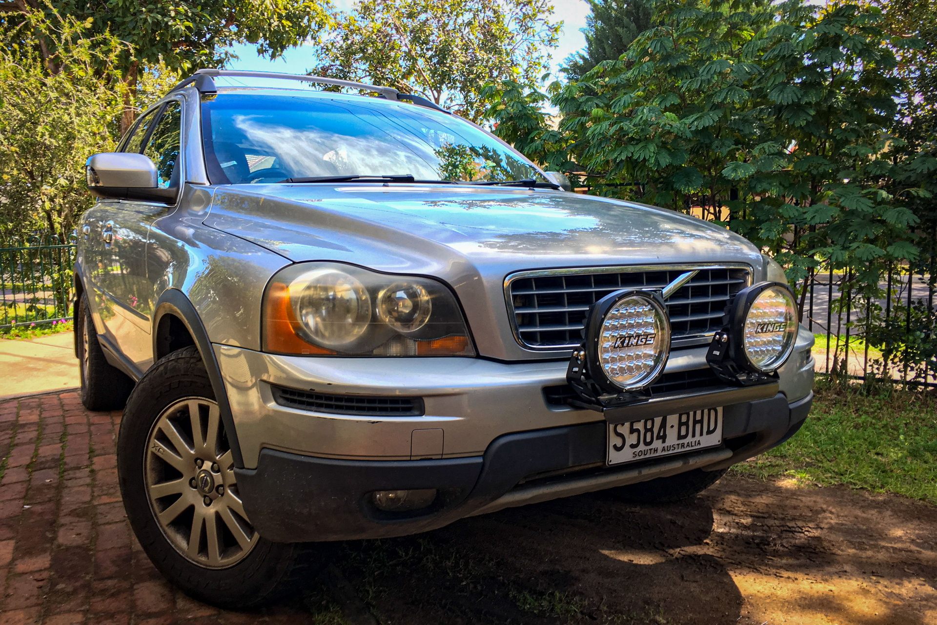
The Result

Let me know if something is unclear and I'll edit or provide further pics.

