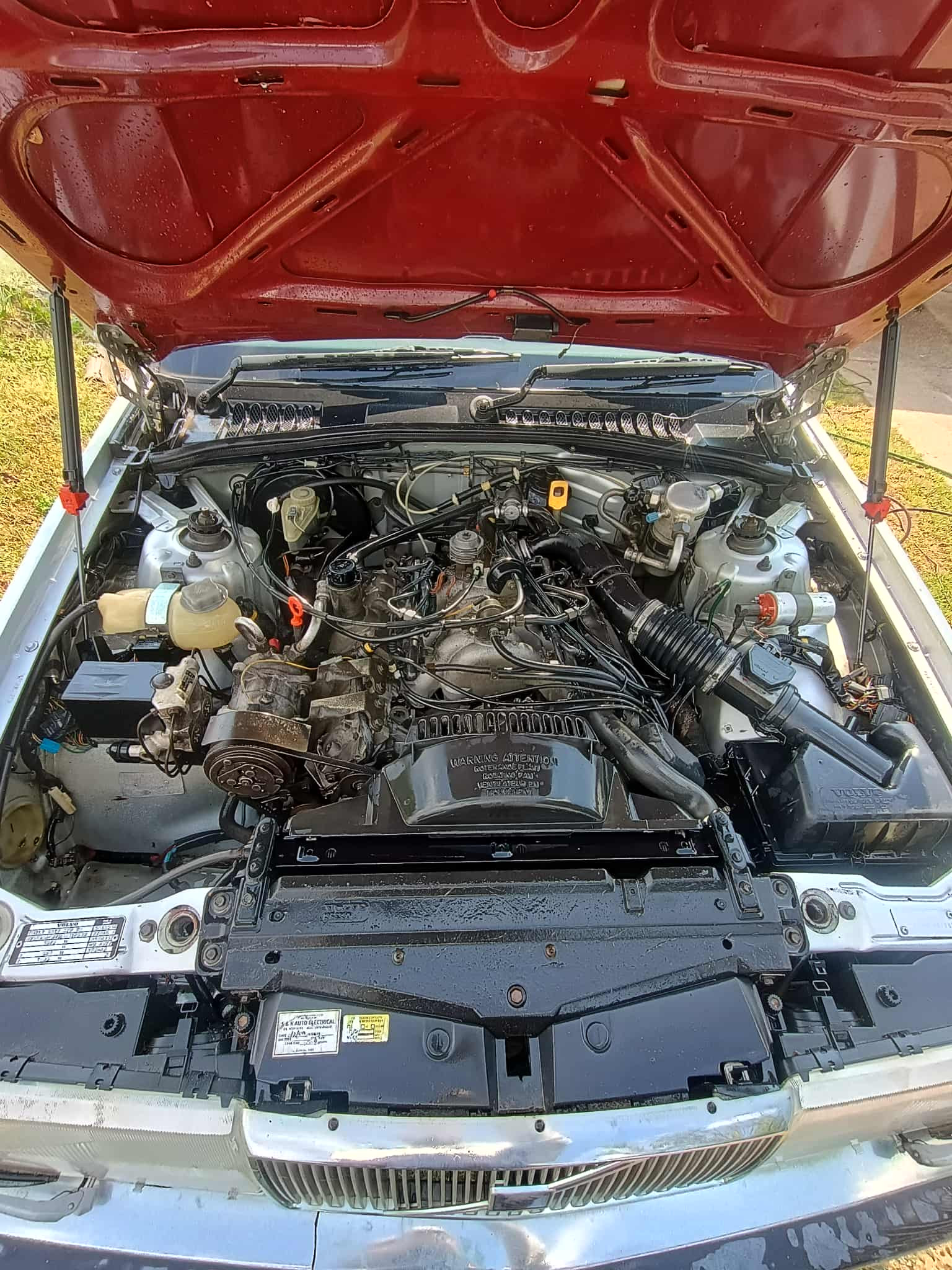
Oh gawd; that's the horrible LH 2.2 system with the B280F….. With an EZ-115K ignition system.
Same setup as I've got in the 780, but wired differently.
TP 31788/1 is the Green Book for these gadgets. I only have it on a USB stick from which I can't take screenshots. 🙁 So you'll get a blow-by-blow description of the circuit paths, below.
Check that your dizzy cap and leads aren't corroded AF. (that's caught me before)
The dizzy cap is a total Kyle's Mom in D Minor to remove from a B280. If the dizzy cap's okay, read on.
Testing:
Go looking for +12V with the ignition switched on -
/Fuse #31 feeds +12V to the fuel injection relay, terminal [1], yellow-brown wire.
/ Check your Radio Suppression Relay and FI relay.
/Terminal [3] of FI relay (blue-yellow wire) feeds the Radio Suppression Relay coil, via A-pillar post terminal [9]. If there's no +12V at [3] of the RSR, the relay won't operate and thus there'll be no power feed to the coil.
/Red wire from battery +ve terminal feeds +12V to term [4] of Radio Suppression Relay; green-red wire on term [3] of RSR becomes a green wire at strut tower terminal [6] which them becomes a blue wire to the coil's terminal [15]. If the RSR isn't working, you won't get +12V at [15] at the coil.
/ Blue wire from 15R (at ignition switch) feeds +12V to pin [4] of the igniter, & pin [6] of the EZ-K.
Good luck!