Well its been a little while, but a few things have been accomplished since my last posting..
The exhaust has now been sorted, and it runs at around 95 db at 4000 rpm, so its a bit more civilised, and around 85 db at idle, which given that the db scale is logarithmic, means it is now 10 times quieter than before at idle, essentially means that the neighbours can hear it, but won't get annoyed by it. The induction roar is set to get louder however… A preliminary test on the dyno (before some minor - but still annoying - technical issues truncated the session) indicated a significant power loss with the pancake filters. I am now going to make some bespoke ram tubes (which will run lightly oiled sock filters) out of aluminium. I got hold of some 22.5 degree mandrel bent aluminium of the correct size (1 and 7/8 inch ID, that is 50.8 mm OD tube with 1.6 mm wall thickness). I will have to angle the ram tubes forward slightly since the rear one will otherwise foul on the brake master cylinder. It seems no one makes ram tubes for the unusually sized HIF 7 SU carbs anyway, no matter, nothing the use of an AC /DC TIG welder can't sort out.
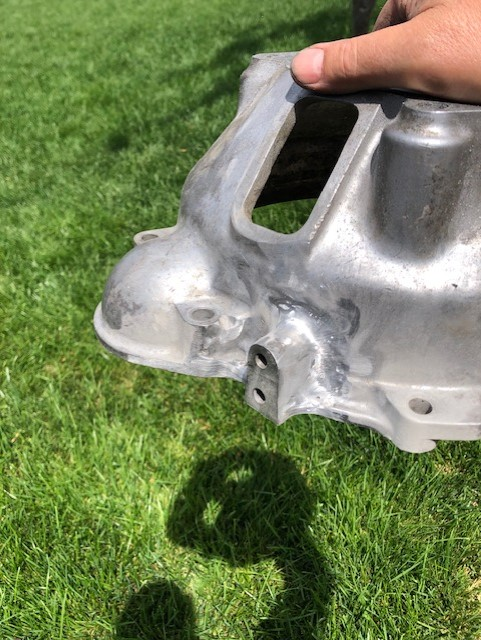
Speaking of the TIG, the long awaited M410 transmissions arrived from the US recently, one of mine was from a 164, and the other an M410 sourced from a 1970 1800, with the correct B20 type bellhousing. The bellhousing is only 'correct' for either 140's or the aforementioned 1800. In a 120 series car, some modifications to this unicorn bellhousing was deemed necessary. Receiving technical advice from the ever helpful Andrew White (of Targa Tasmania fame, his M410 equipped 122S car now owned and very successfully raced by his former navigator extraordinaire Ash Yelds), he stated that welding is necessary to attach the hydraulic slave cylinder to the side of the bellhousing where the cable activated system was previously situated. For this I copied the exact location position from a 122 type bellhousing. My AC TIG only goes up to 200 Amps, but that was just enough to get the job done. I suspect that 240 to 260 amps may have been better, but whatever….. Here is a shot of the finished result after cleaning up the appearance of the weld with a small 30 mm flap wheel. (This is also my first attempt at being a 'hand model'!)

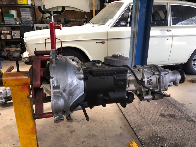
The small hydraulic clutch type fork was a tad tricky. I solved that by drilling a hole approx 10 mm away from machined cast iron housing that bolts to the gearbox from inside the bellhousing. The only problem being that the 1/4 inch UNC threaded cap screw which is then situated under the clutch lever cannot be accessed to tighten it. I ended up using a standard hex head high tensile substitute for that one. The bolt used to fasten the clutch pedestal was an M8 with a countersunk head. It had to be tightened first, prior to tightening the 1/4 inch hex head underneath it when attaching the bellhousing to the gearbox, very, very fiddly., but got it in after about 30 minutes or so. The bulge on the upper right side of the bellhousing where the mechanical clutch fork bolts too has to be removed since it would foul on the narrow 120 transmission tunnel. A standard long gear shifter gearbox top (from an M41) bolted straight to the top of the M410, which is handy to say the least.
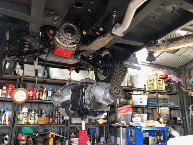
Installation of the M410 into the car ended up being a pain in the neck. The narrow 120 transmission tunnel doesn't like to accept a transmission with its bellhousing still attached, much easier to do the bellhousing first, then the gearbox later, but not possible with an M410, due to the bolts attaching from inside the bellhousing. Eventually, I managed to tilt the engine far enough to finally allow the gearbox to go in.


Once all this is done, the new radiator goes in, and the final wiring gremlin (left indicators) gets sorted, and the new carburetor rams tubes are made, then its back to the dyno place for final tuning..
Will post pictures of the new induction setup once its done..