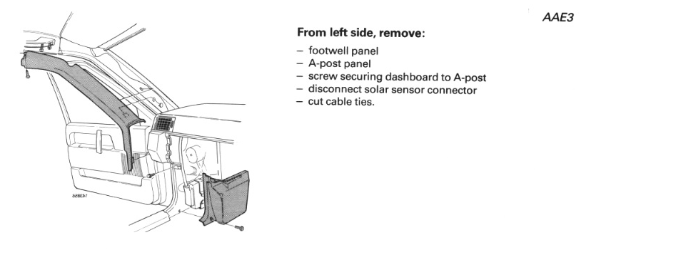
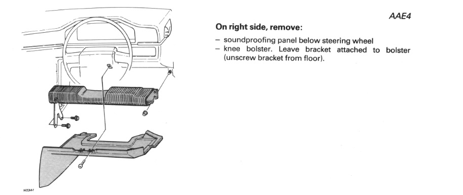
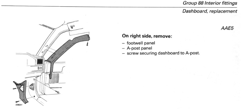
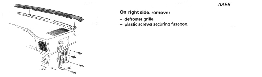
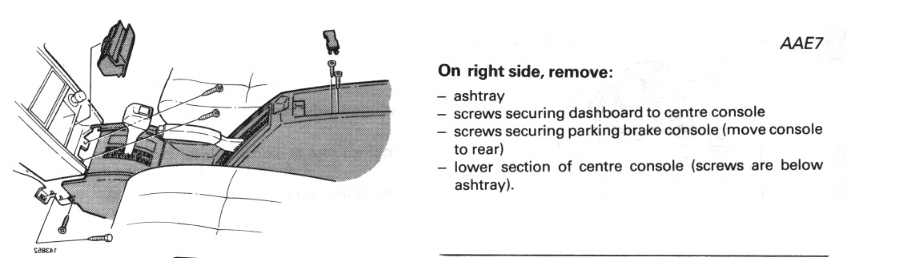
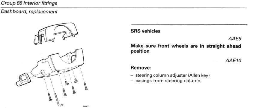
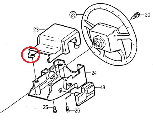
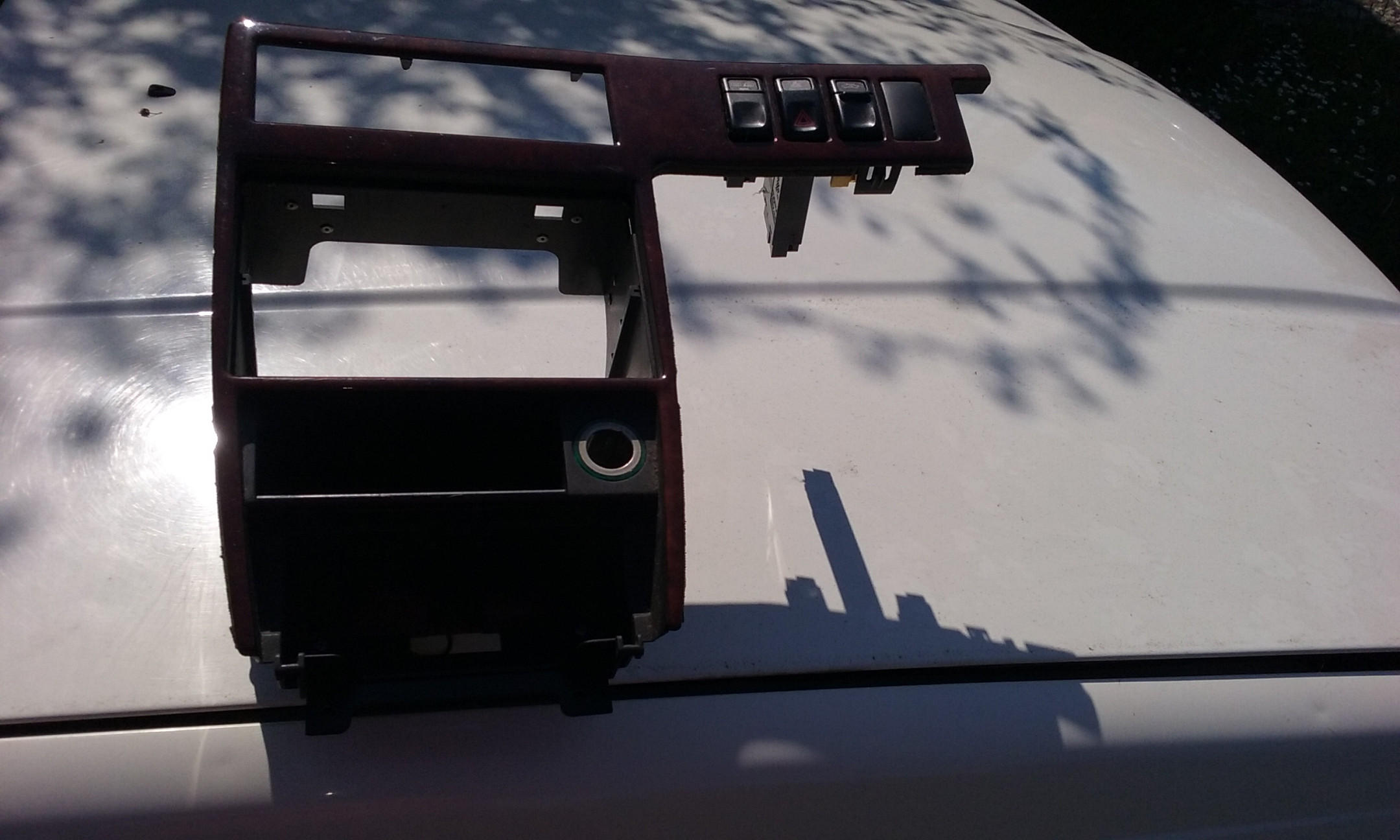
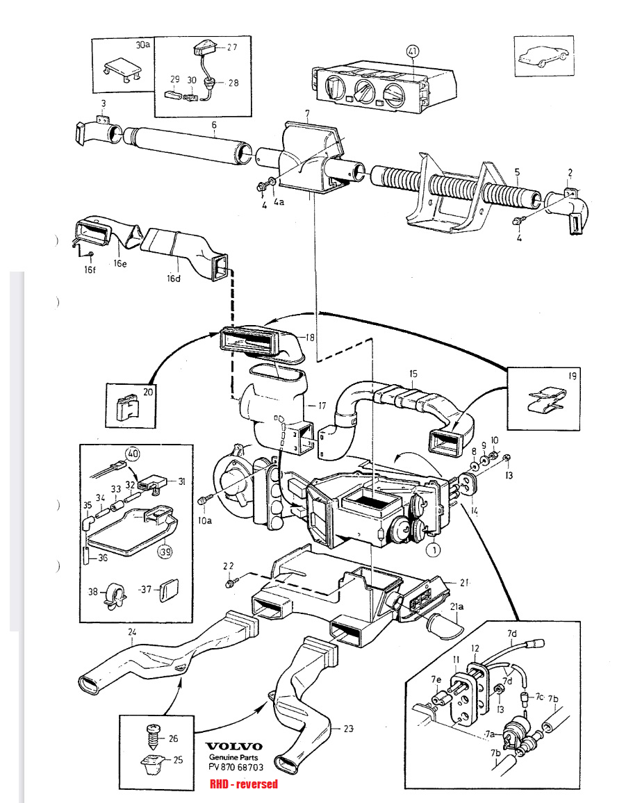
Steps AAE1 & AAE2 from the Green Book - image reversed:
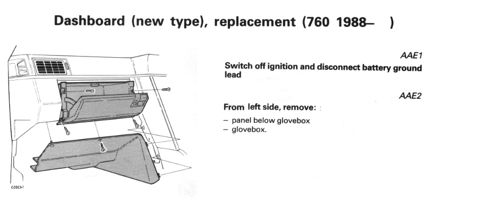
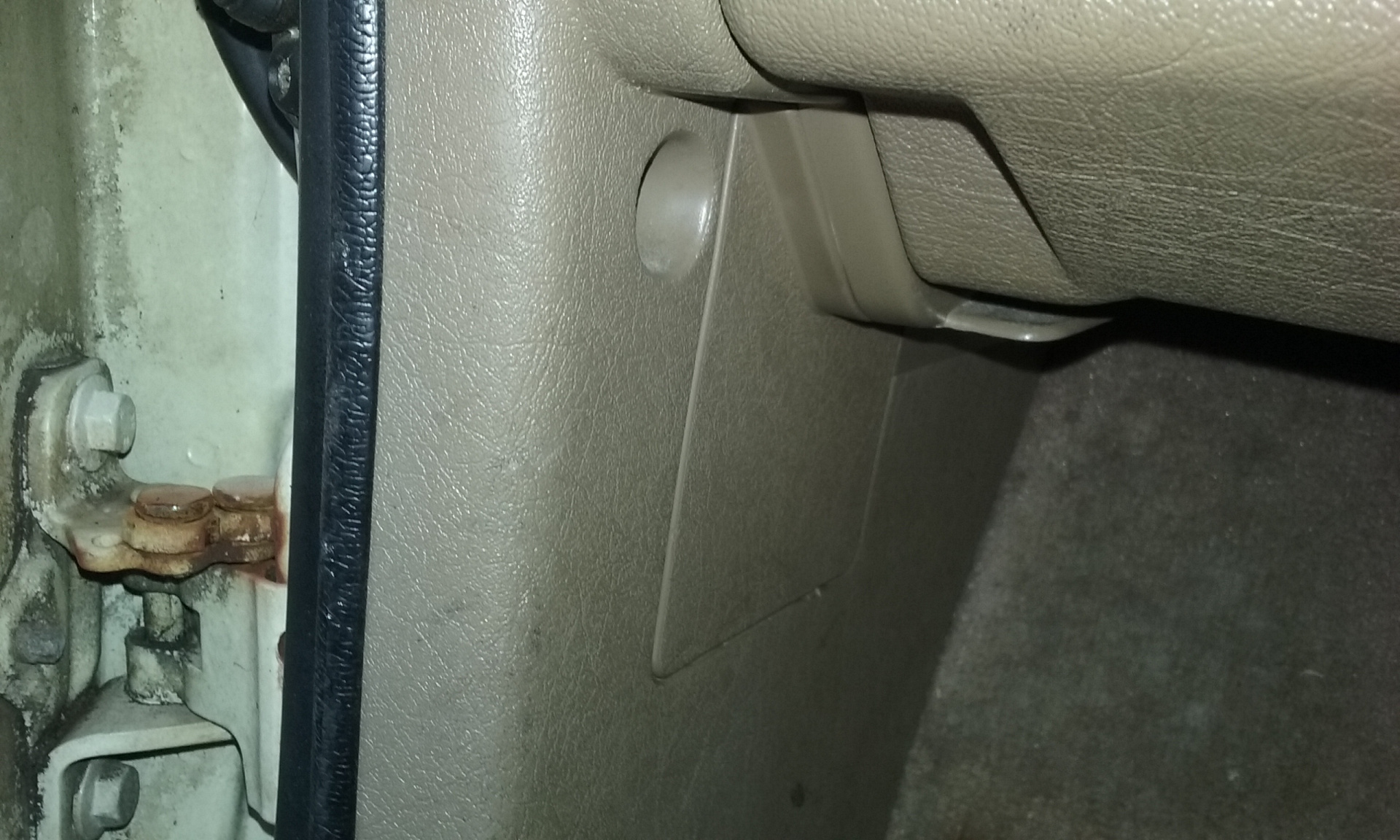
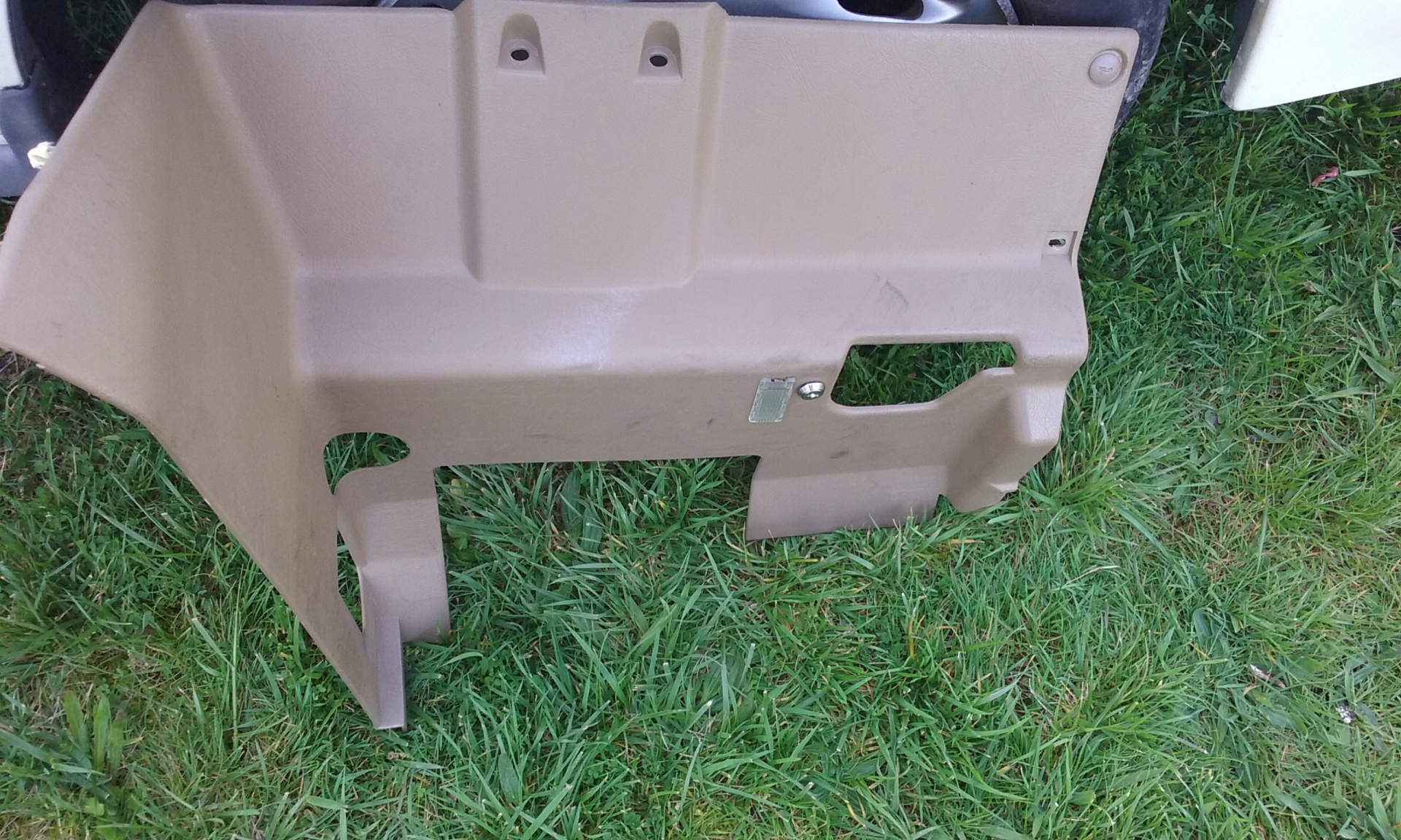
Notes: panel below glovebox removal
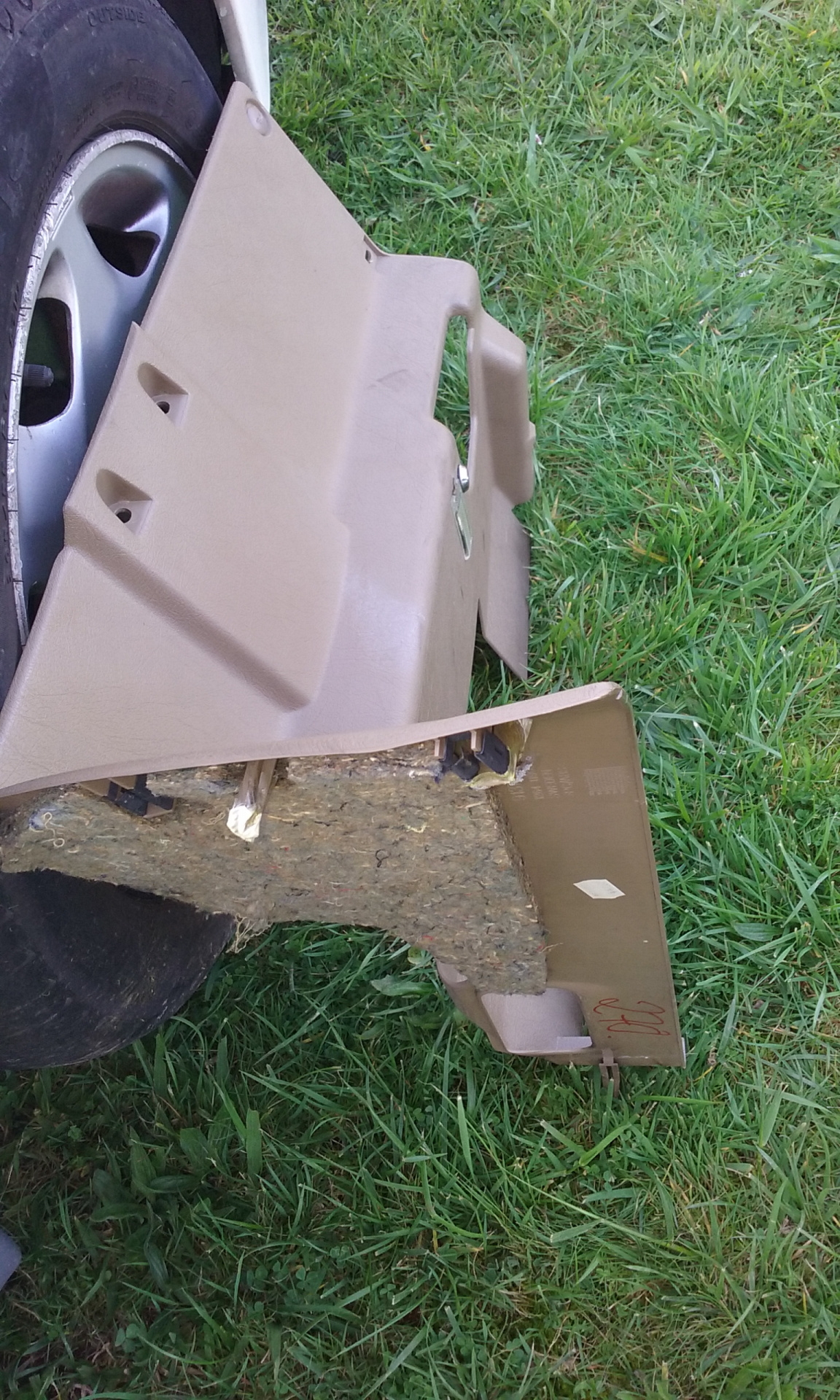
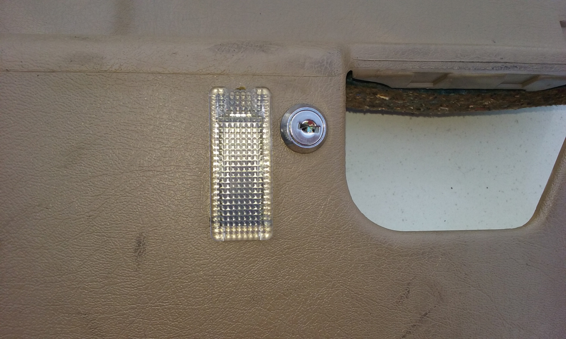
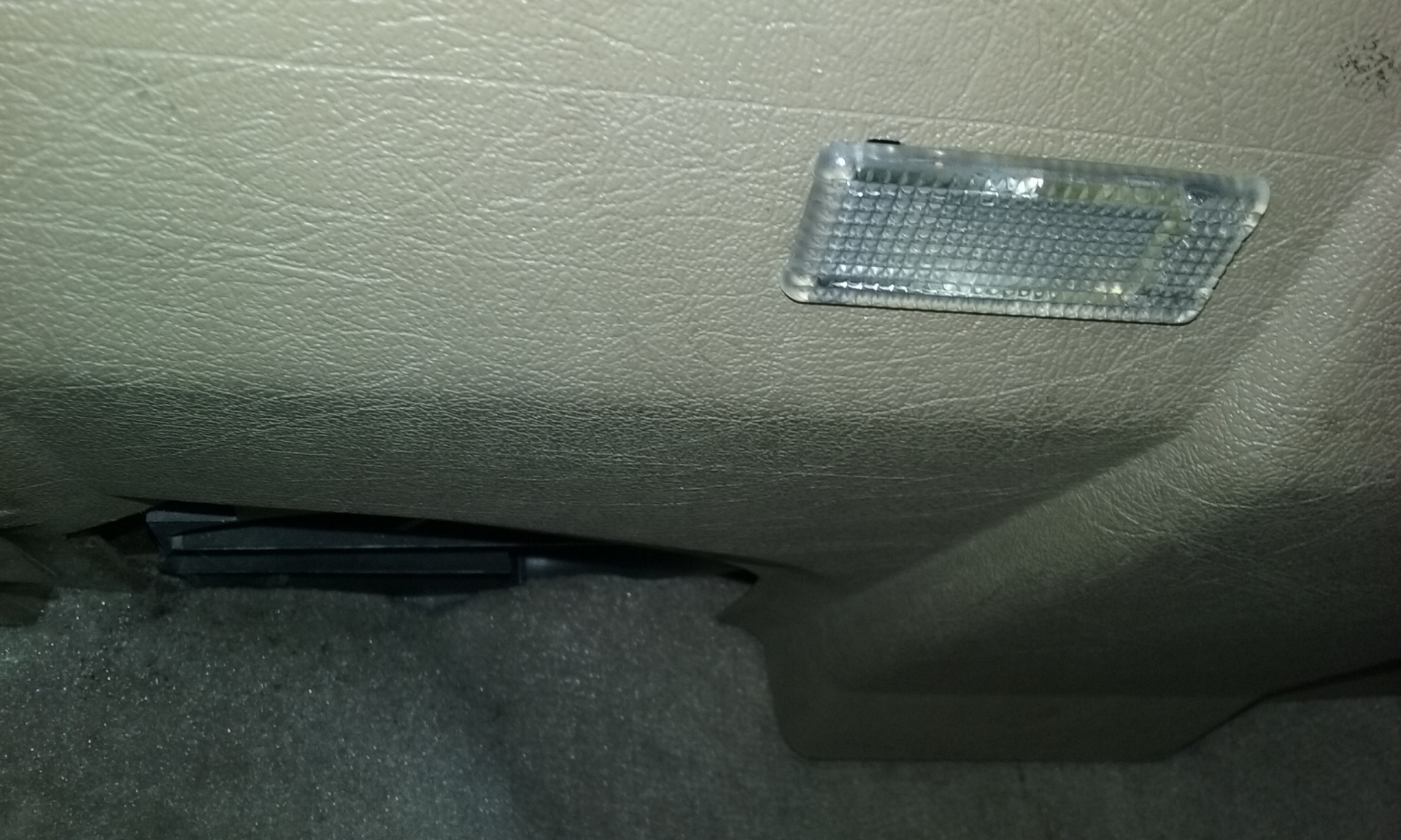
Once the panel is off, you'll need to disconnect the foot-level courtesy light. There's a cable tie (of course) which holds the connector to the lamp body.
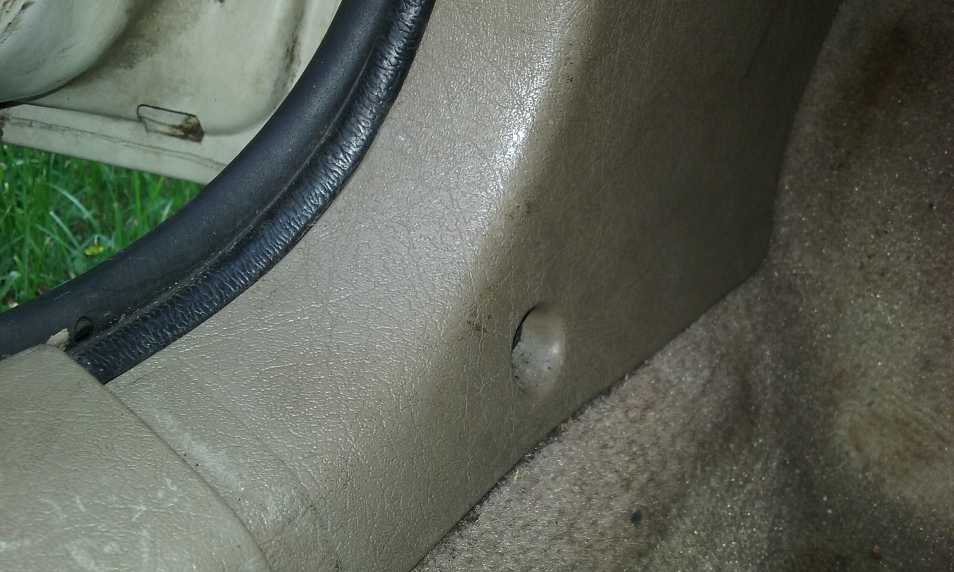
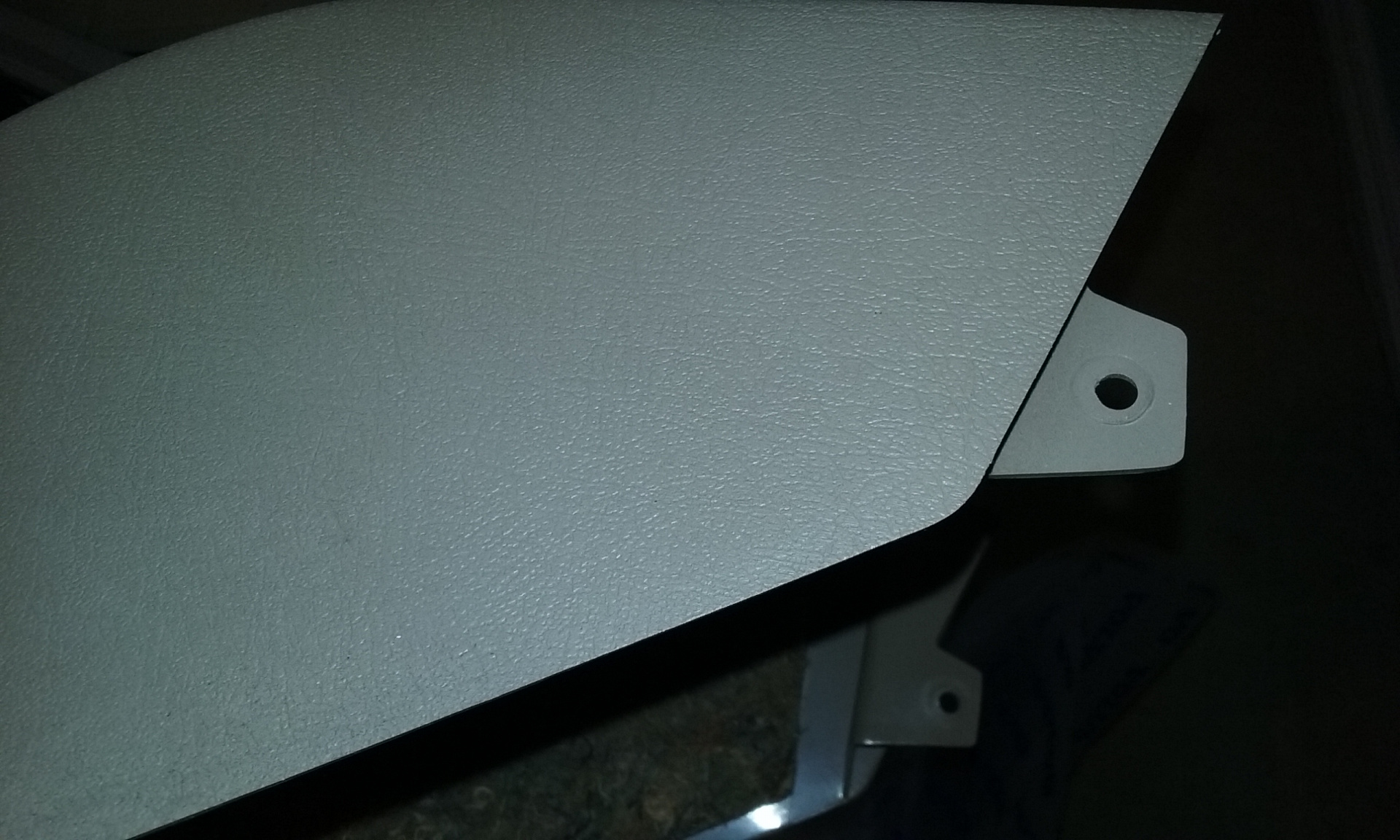
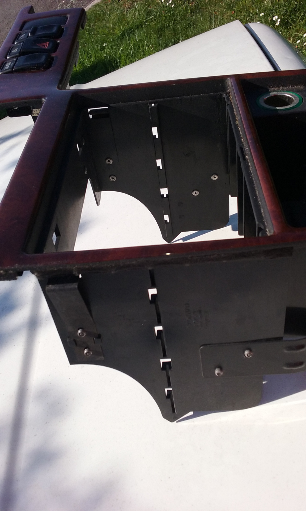
Notes: glovebox removal
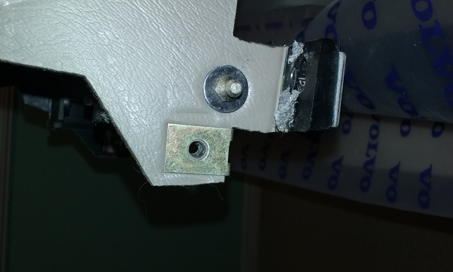
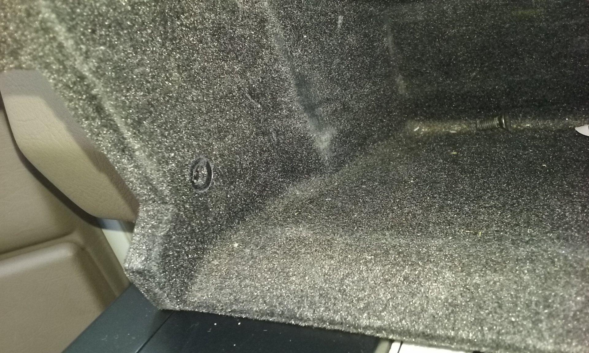
Not all the glovebox screws are shown in the LHD diagram above. There are two more screws inside the glovebox itself. This is one of them - the one's inside the glovebox on the LH side. There's another on the RH side.
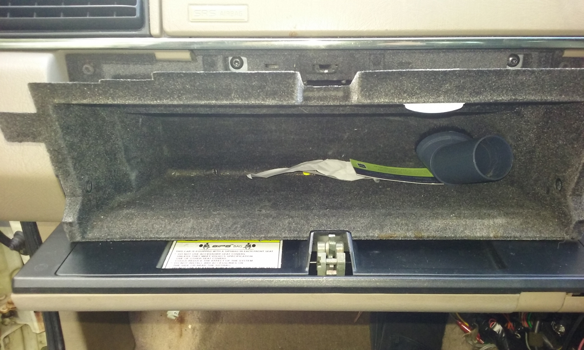
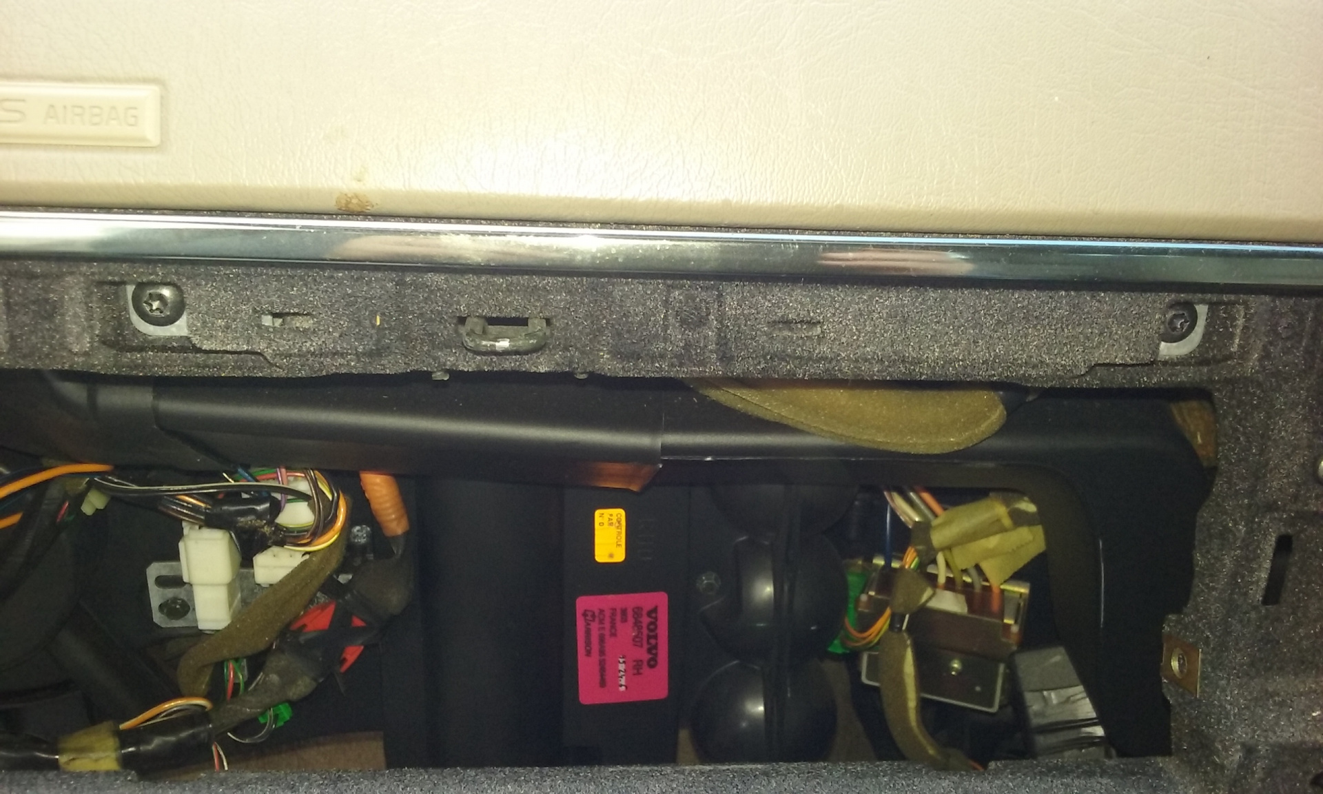
Also, when you remove the glovebox, you're only removing the box itself at this point; it's not like a 740/940 where the whole glovebox door and box are removed as a single unit. See those two Torx screws just above the glovebox lip? They hold the passenger's side air bag unit in place.
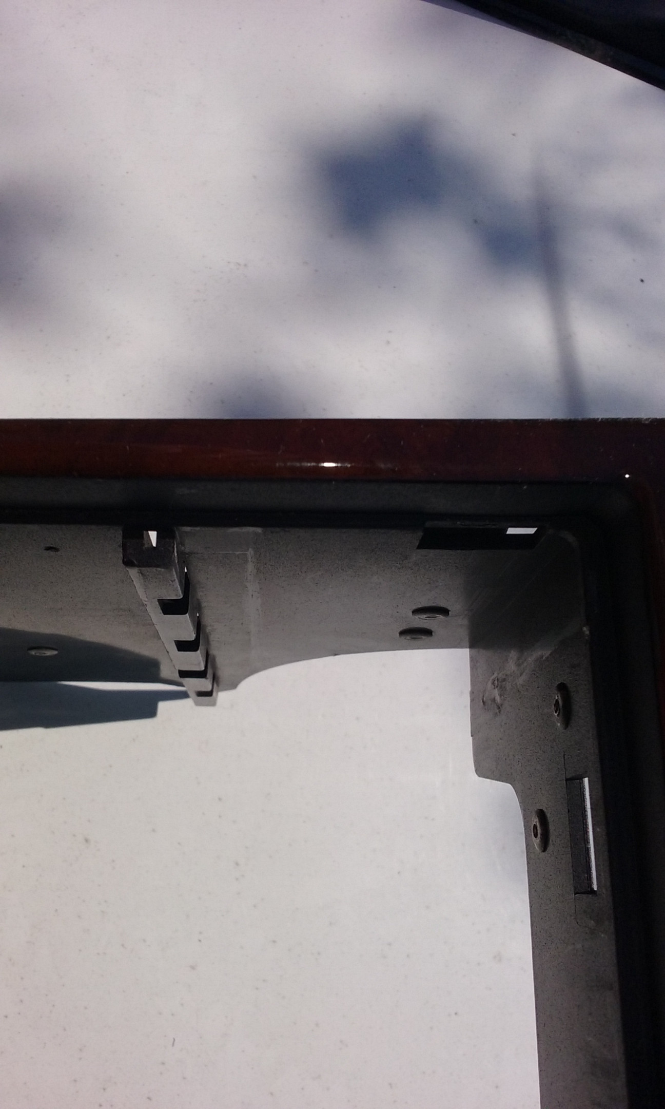
Glovebox door frame removal; passenger side airbag removal; LH duct removal - not covered in Green Book
Remove these two T25 screws, and the airbag lifts up and out.
Carefully unplug the airbag, and now you have a big hole in your dash, plus a glovebox door (not in pic) getting in your way.
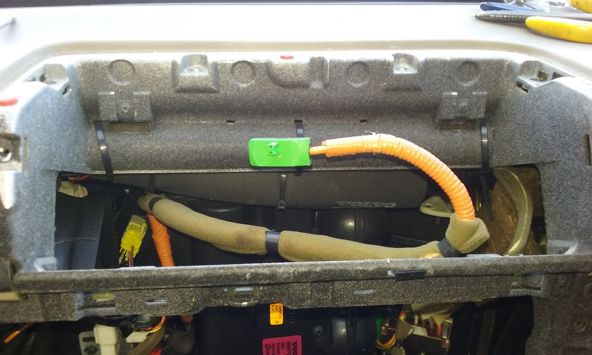
The airbag support / glove box door support frame is held to the dash proper with a series of T10 screws.
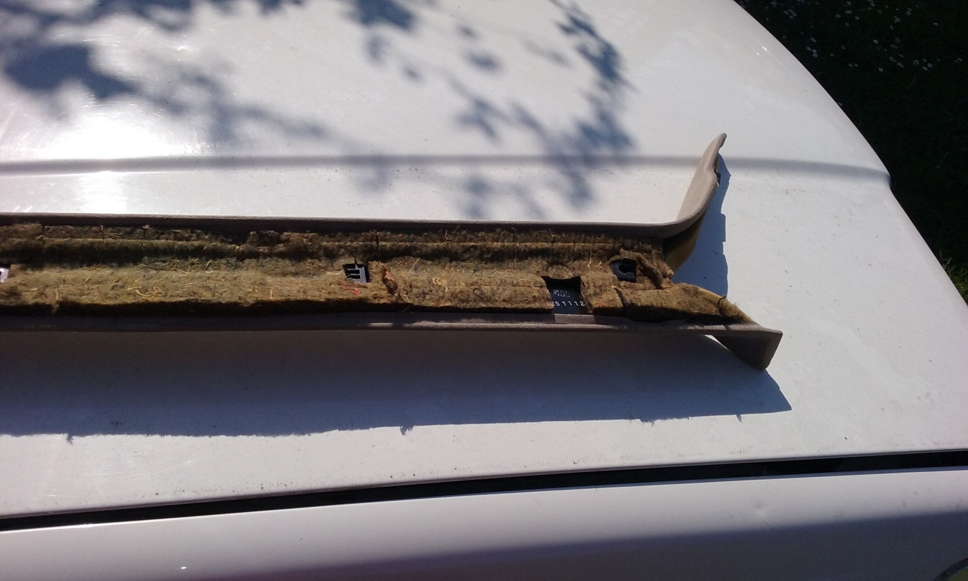
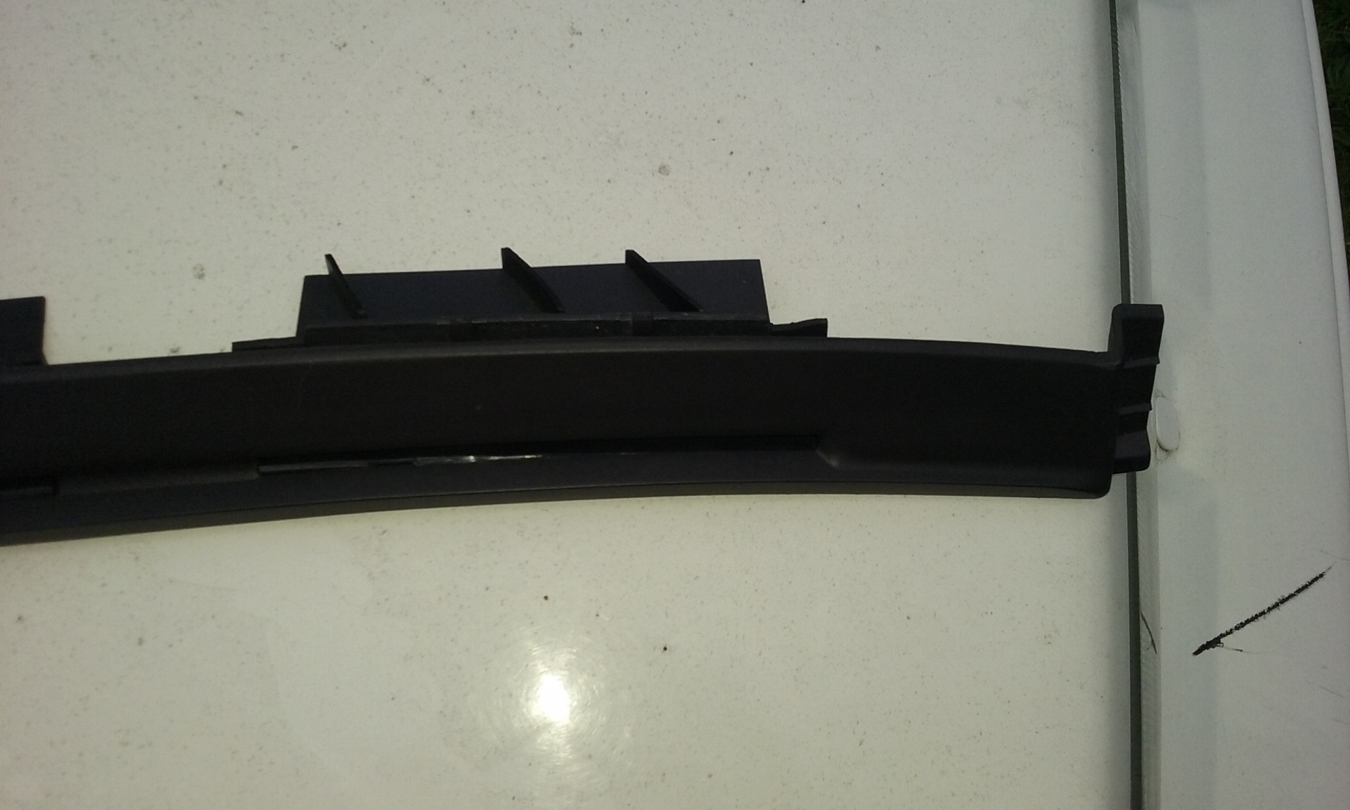
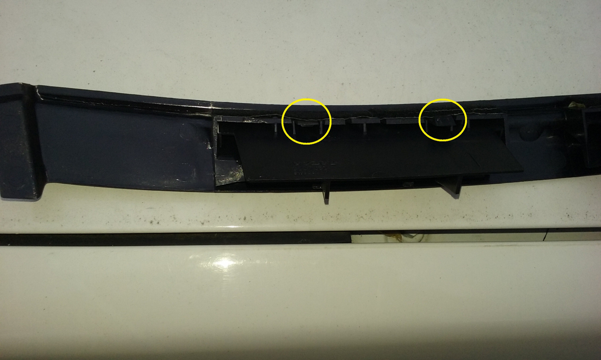
To remove this frame, first remove the shiny curved metal trim piece which runs around from the LH air vent to the centre of the dash. It's held in firmly in place by one little black plastic mould clip. If you need to replace that metal trim piece, they're different between cars with passenger side airbag, and those without.
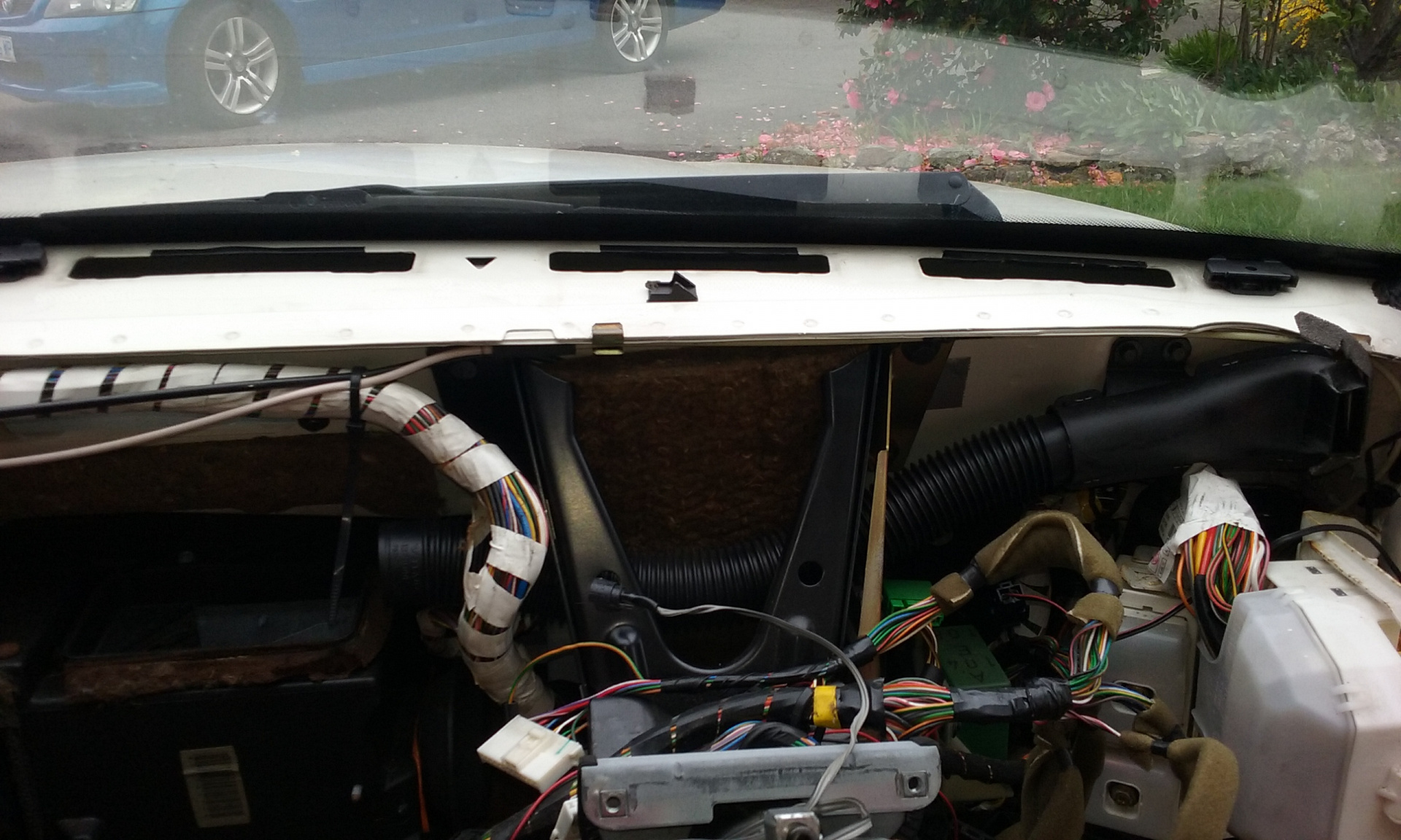
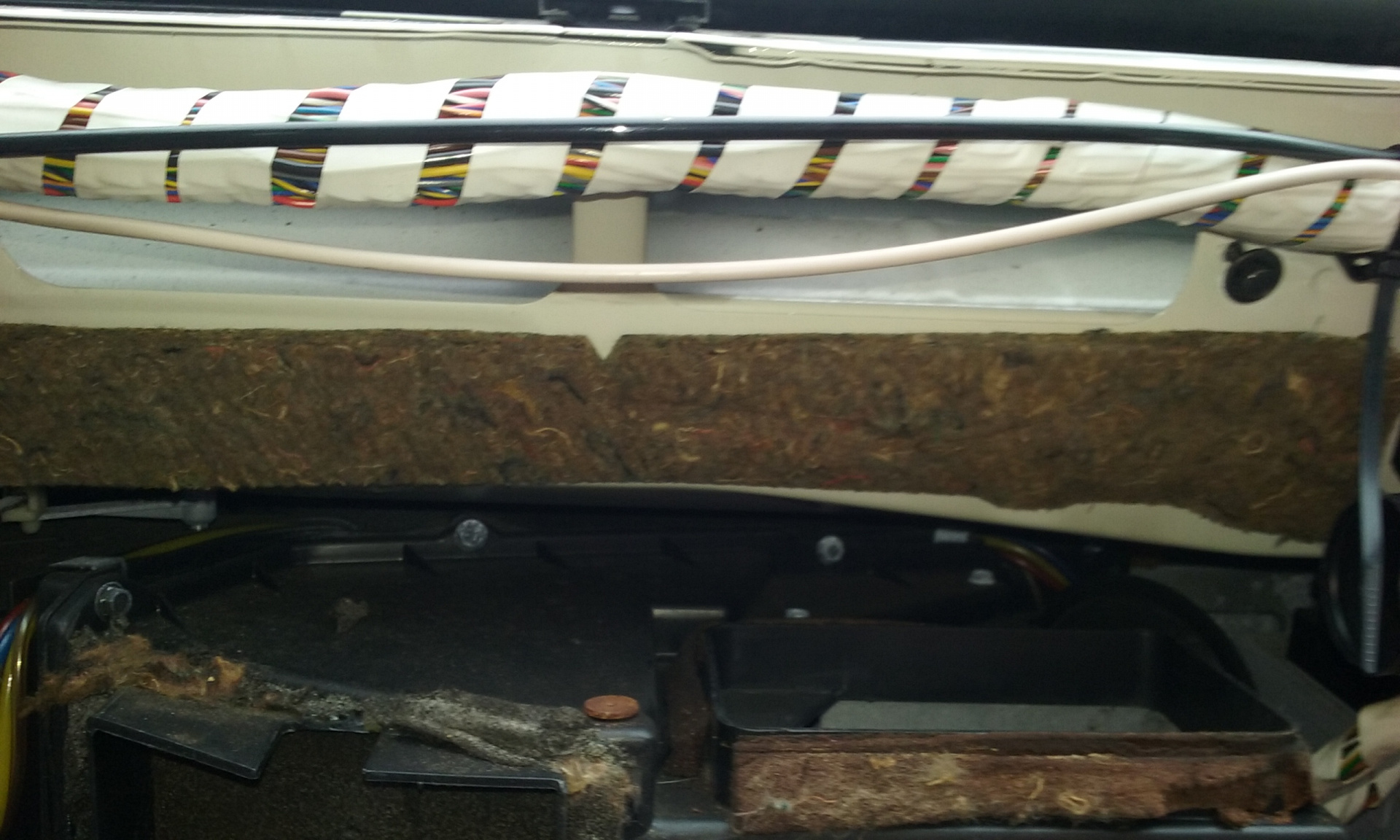
Next, remove these T10 screws, and clip the 3 cable ties which hold a wiring harness to it. One of these in the pic above is partially hidden by the airbag connector; the other two are its companions to its left and right.
There are two more bigger Torx screws near the glovebox door hinge. Then you have an even bigger hole in the dash!
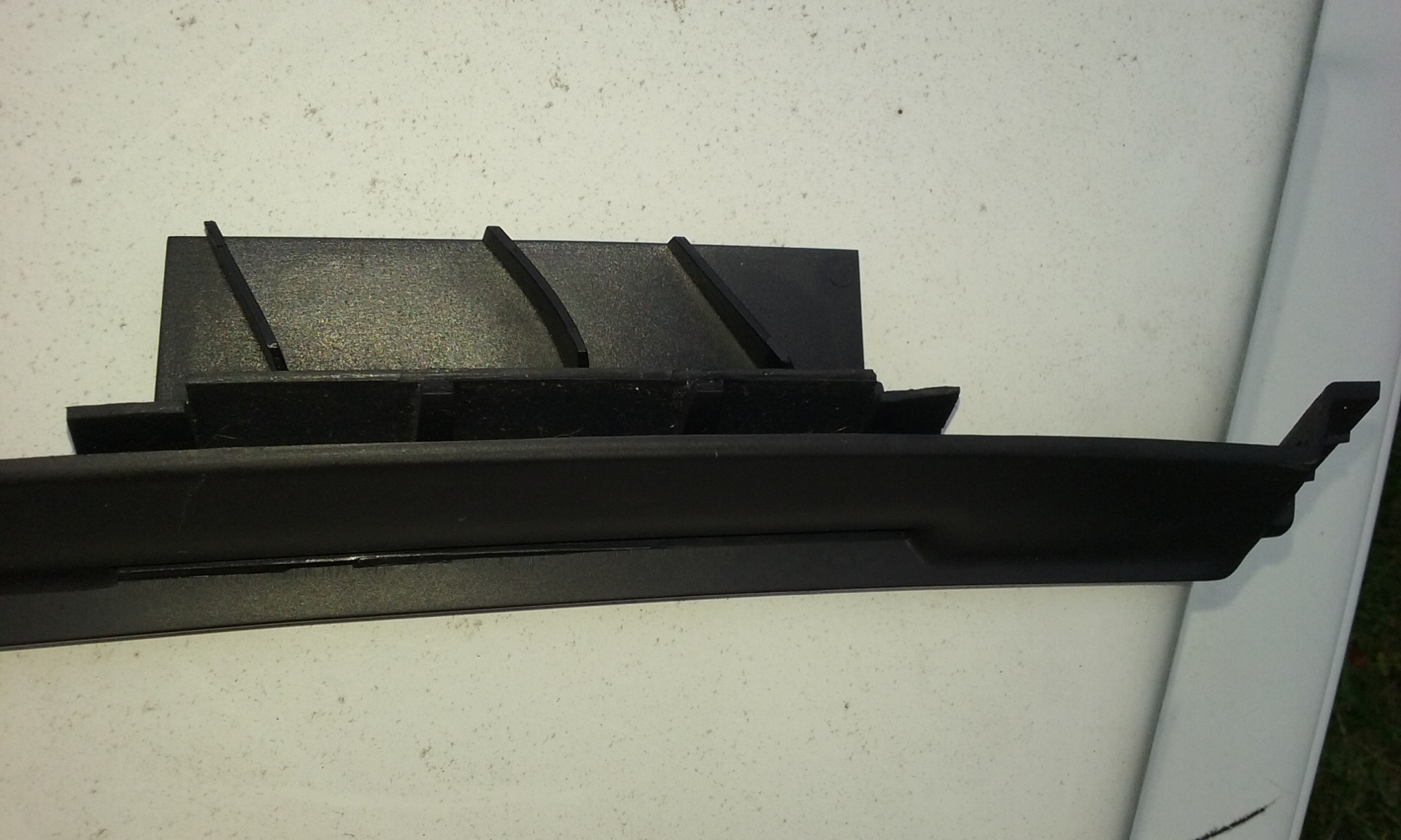
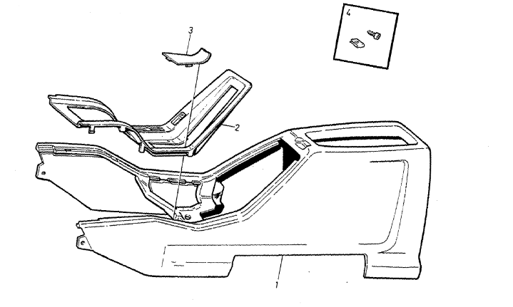
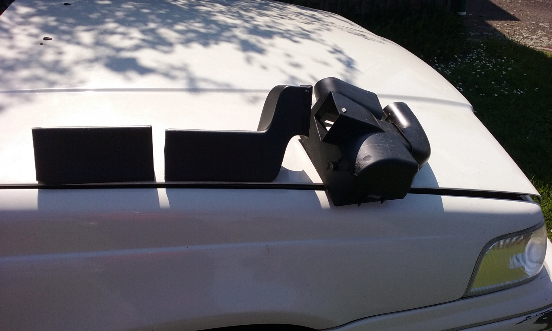
However, this then allows you easy access to the duct for the passenger's face-level vent near the LHF door. It's in 3 parts - the LH side connects to the air vent; the RH side connects to the air mix box, and the large central part is then very easily removable. Pic below shows these 3 of the 4 components once they've been removed.
Dash speaker / tweeter removal and solar sensor disconnection - not covered in Green Book
There's a trick to this:
Carefully pry the little plastic cover up and off the speaker grille.
There are then two T25 Torx screws which hold the plastic frame which hold the plastic cover in place; remove then carefully. (These were very badly broken on my car, and these parts are NLA).
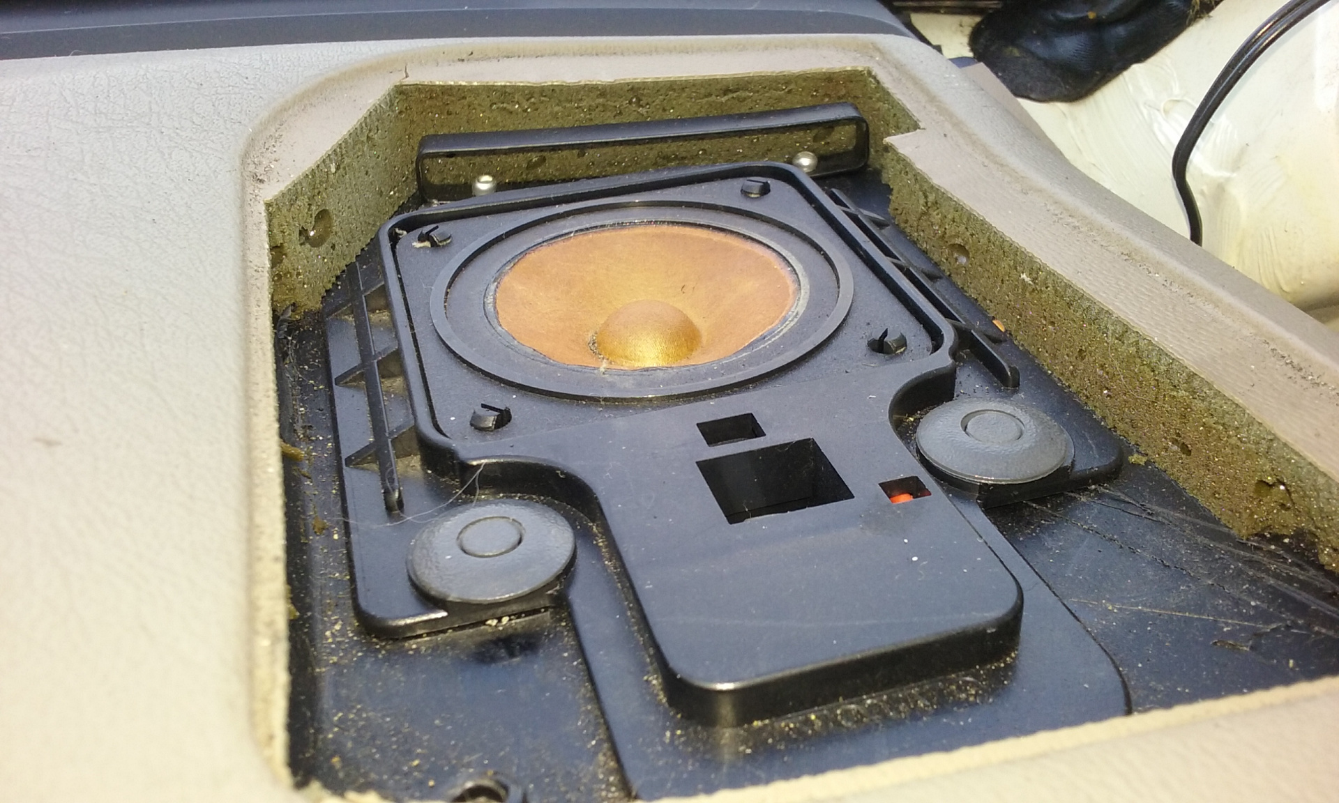
To remove the tweeter speaker, use a screwdriver to gently push down the centres of those two washer-like clips. The complete clips then lift out. As does the speaker. Which means you can disconnect the speaker connection.
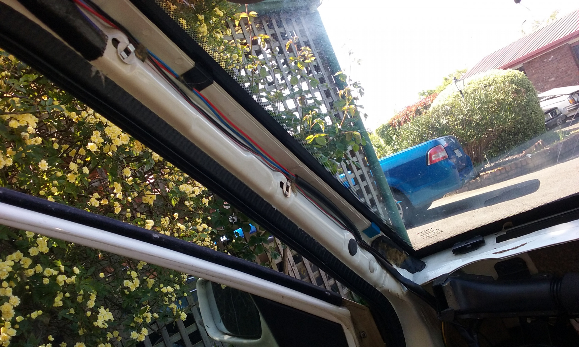
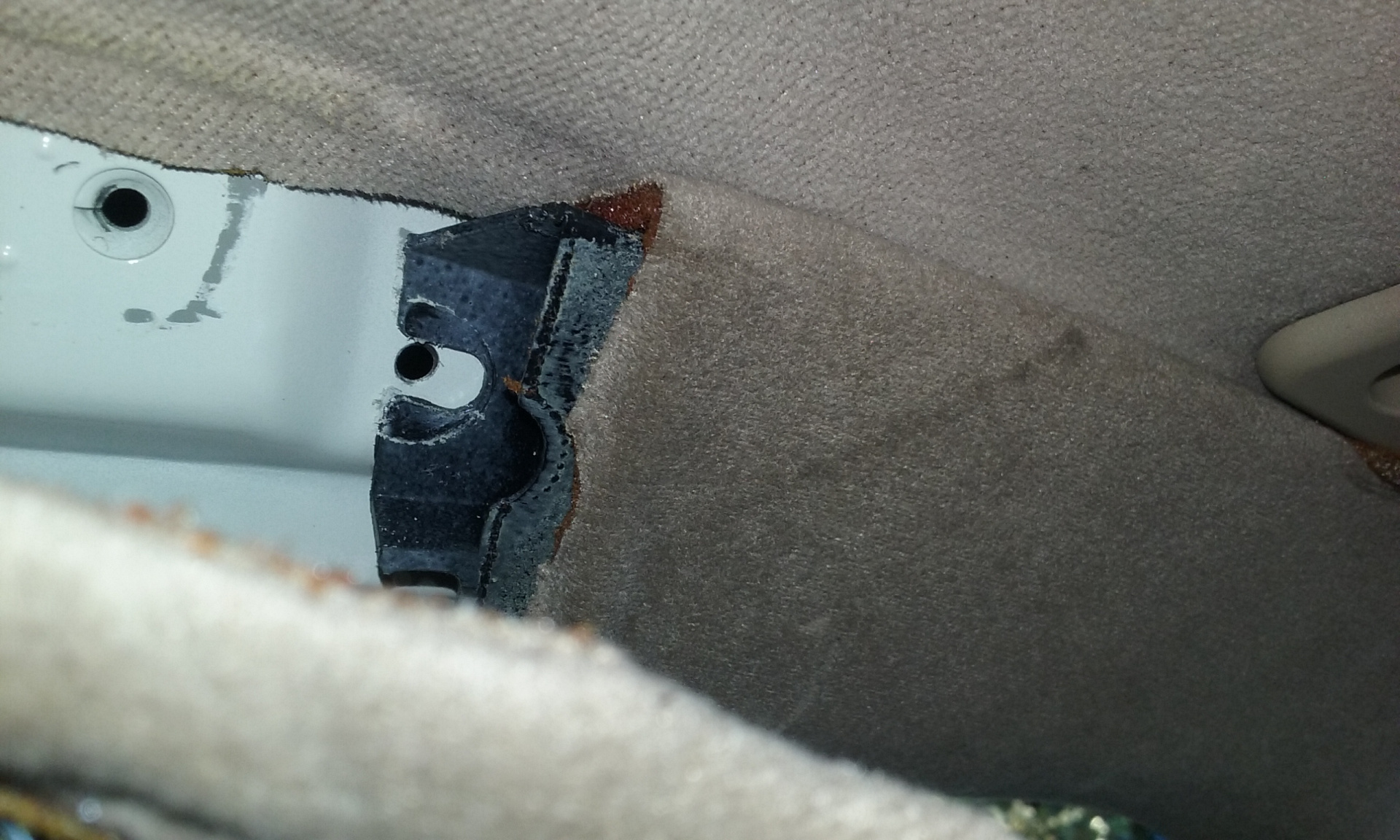
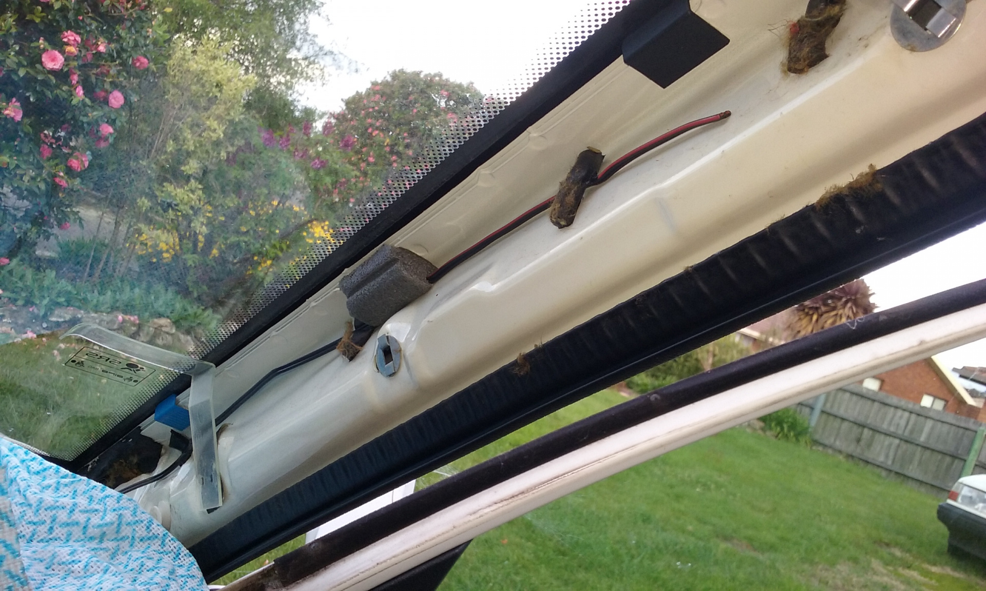
The solar sensor for the ECC sits on the LH side speaker grille (different from 940), and there appears to be a squarish hole in the dash through which this sensor's plug will pass though.
I have some bad news: it doesn't, so firstly you will need to disconnect this sensor from the harness. That's easy to do now that you have a great big hole in the dash.
Of course, be prepared to snip the ubiquitous and inevitable cable tie which holds this connection in place.
When you eventually remove the dash panel, the LH speaker grille and this sensor will be dangling, unless you're prepared to undo the sensor's plug from the sensor (I didn't).
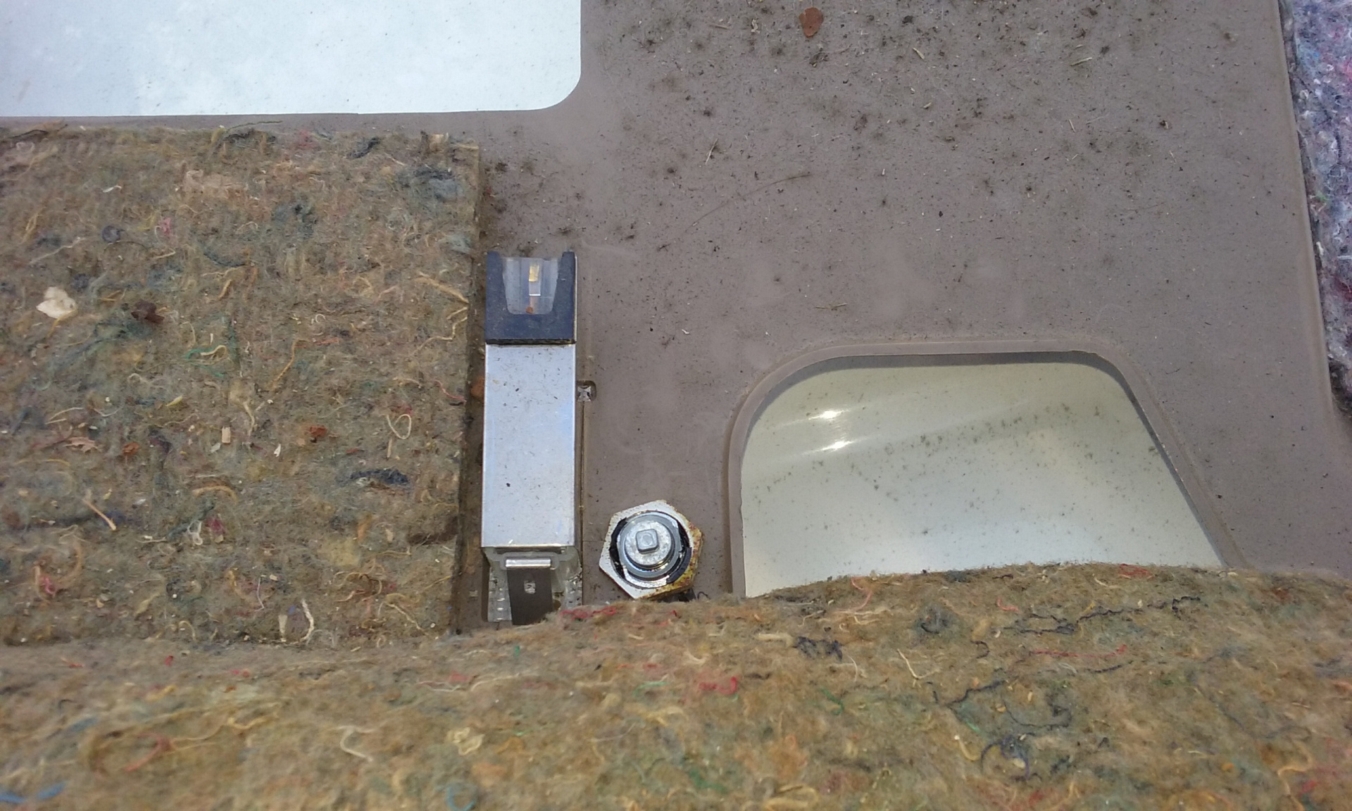
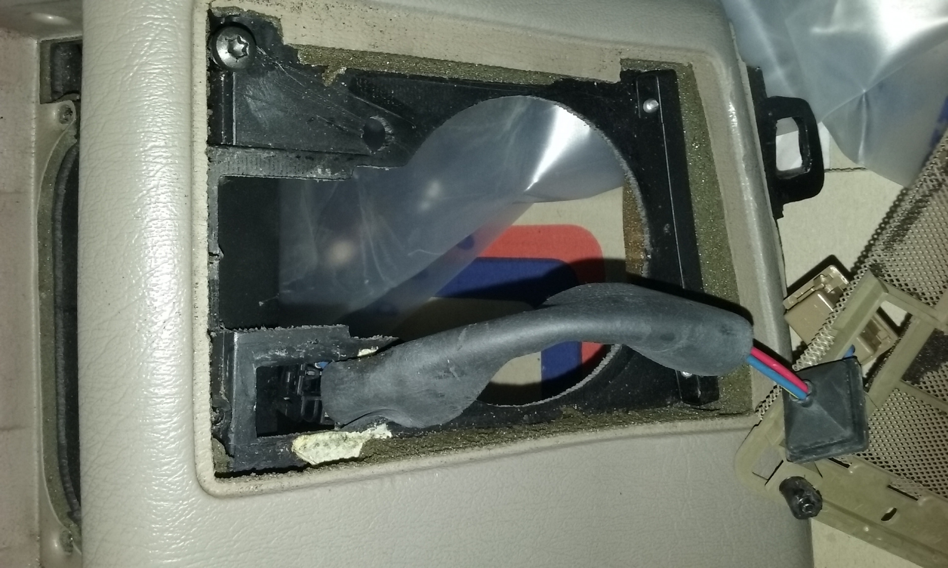
Picture below shows how the solar sensor's plug is too big to fit through the square hole.
There's more to remove from the LH side of the car, to be covered in Step AAE3.