It has been a while since I contributed anything substantial so thought I would add this.
I have a 1989 Volvo 240 wagon, fitted with factory key operated central locking. I wanted to add a cheap, key fob/remote to the existing sytem rather than change it out for a full aftermarket system.
I chose a Steel Mate 386M unit from my local Jaycar. It was around $50 and comes with 2 remotes, the receiver/central locking module and wiring harness.
The remotes are simple and seem to be of reasonable quality and the range is good.

There are 2 main issues to deal with when trying to fit this system.
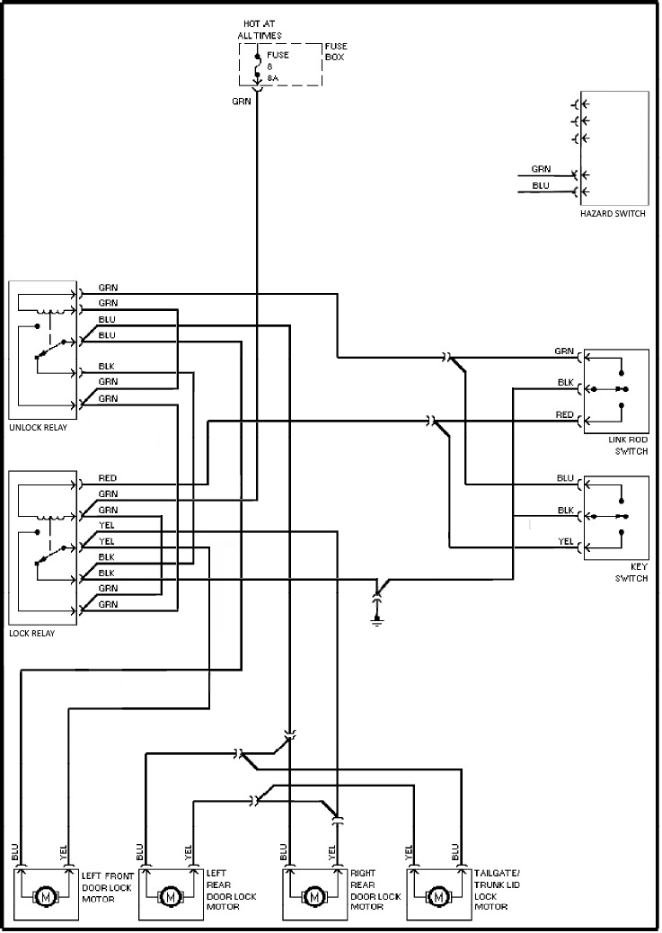
The 240 does not have a solenoid in the drivers door, this is because it is normally locked manually, the other doors, including the boot or tailgate are locked electrically when actuated by the either of the switches in the drivers door (one in the lock button and the other in the keylock barrel)Volvo use an earth pulse system to actuate the door solenoids. Most aftermarket units, including the 386M use a 12v+ pulse. Of course you could try and track down a unit that is capable of providing an earth pulse but I have found most dont work this way and it can be difficult to know if they do before actually purchasing and testing.
Issue 1
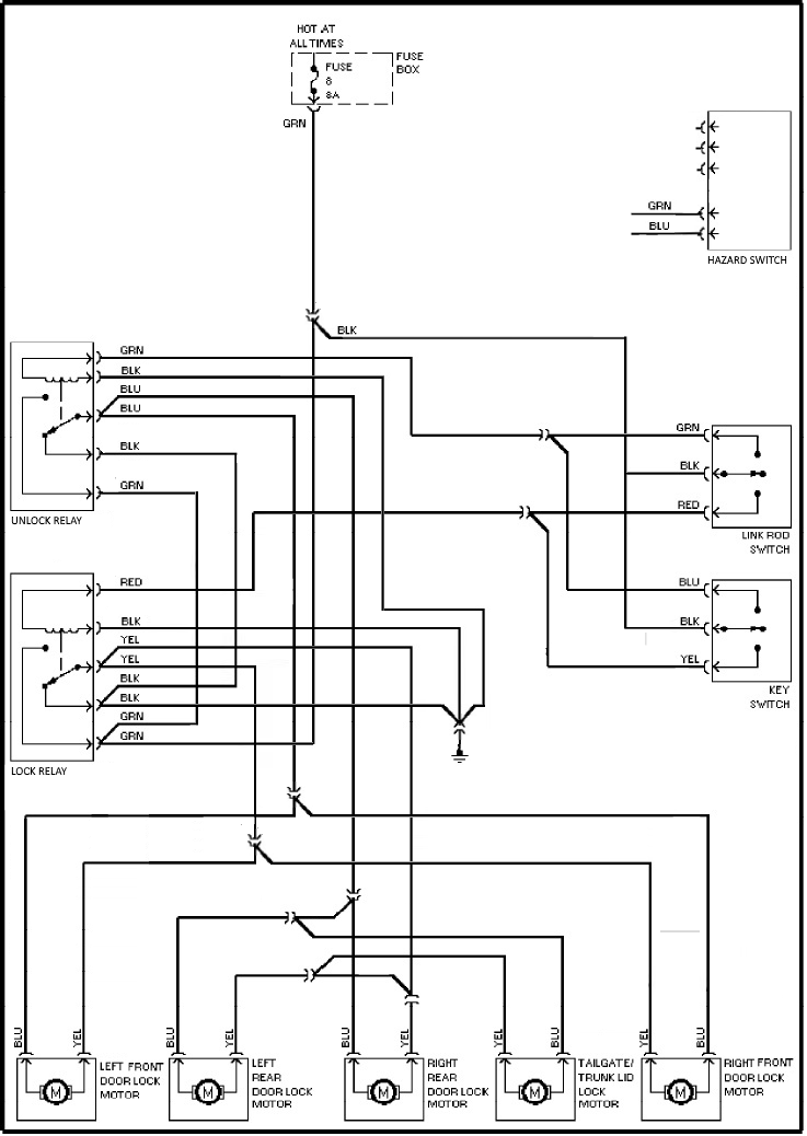
Dealing with item 1 is easy. If you happen to have a left hand drive 240 sitting around :) you can take the solenoid, actuator rod, and door wiring from from the passenger front door, this would bolt in. As this is unlikely you can take the same items from the passenger front door of a rhd car, the mounting bracket can be reversed and it will bolt in, you will need to get a bit creative with the rod as it has some complex bends but with a little perseverance you will have a rod that mirrors the one in the lhf door. Run the wiring through into the rhf footwell and put your door back together.
You can then extend these wires all the way across to the passenger side of the car under the glove box, where you will need to splice the yellow and blue wires into the yellow and blue wires running to the lhf door.
Issue 2
One way to solve this problem could be by installing a couple more changeover relays but I chose to convert the earth switched system over to 12v+ switched as it makes for a much cleaner install in the end.
Standard central locking wiring (earth switched):

Modified central locking wiring (12v+ switched) with added drivers door solenoid:

First of all, pull fuse 8 out of your fuse box, everything we are dealing with is powered from this fuse, this will avoid damaging anything while working on it.
Next you will need to gain access to the lock and unlock relays in the centre of the dash. These are mounted up high, directly below the centre air vent. You will likely need access to the top and bottom of these so I suggest pulling out the vent as will as the lower section/ heater controls etc. You can then unclip the relays from the rail and push them up for easier access.
I suggest labelling the relays at this point, the one with yellow wiring is the lock, the one with blue wiring is unlock.
You will need to locate the black ground wire coming from the rhf door, it is relatively easy to locate as there are only 2 black wires in the harness at that point, one from ground to the lock relay then on to the unlock relay and the other from ground into the harness, this is the correct wire. It will need to be cut off at the current earth lug and male spade terminal attached, then set aside, you will use it shortly.
Next, pull the 2 green female spades for pin 86 from each of the relay mount blocks, both relays have multiple green wires so please check you are removing the correct ones, the pins on the relay are labelled. Insert the male spade terminal you just added to the black wire into one of these female spades, both can then be taped or insulated with heatshrink (this is important as they are both 12v+) the second one will not be used. (they can be wrapped together or seperate, it makes no difference)
Now add 2 new black wires from the 86 pins to ground, you will need a female spade on each, these can go direct to ground or can be spliced into the existing ground wires at pins 87a.
You can now reinstall fuse 8 and test, everything should work as it did before but importantly it is now 12v switched rather than earth switched.
The final step.
Once again I suggest removing fuse 8 for this part.
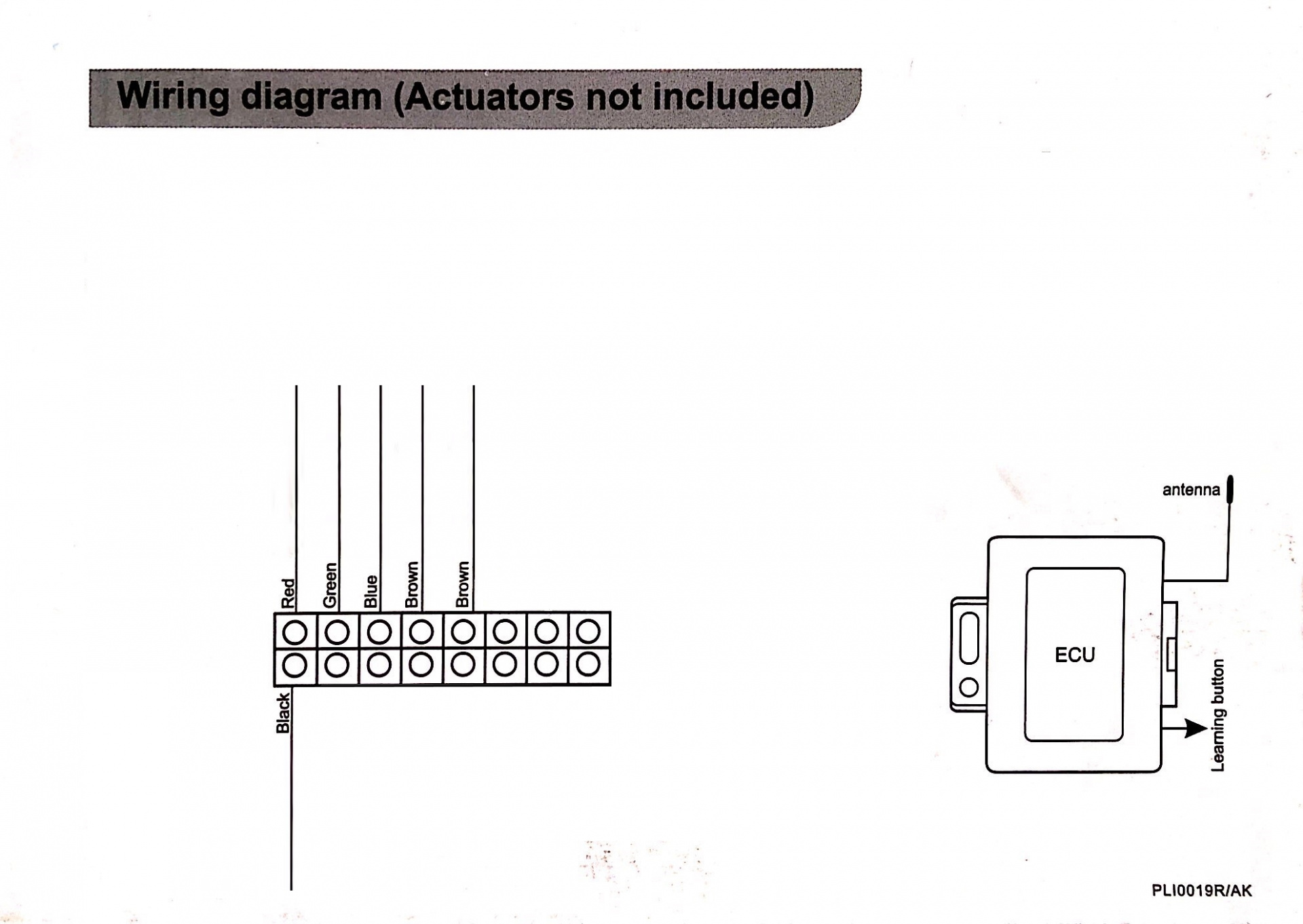
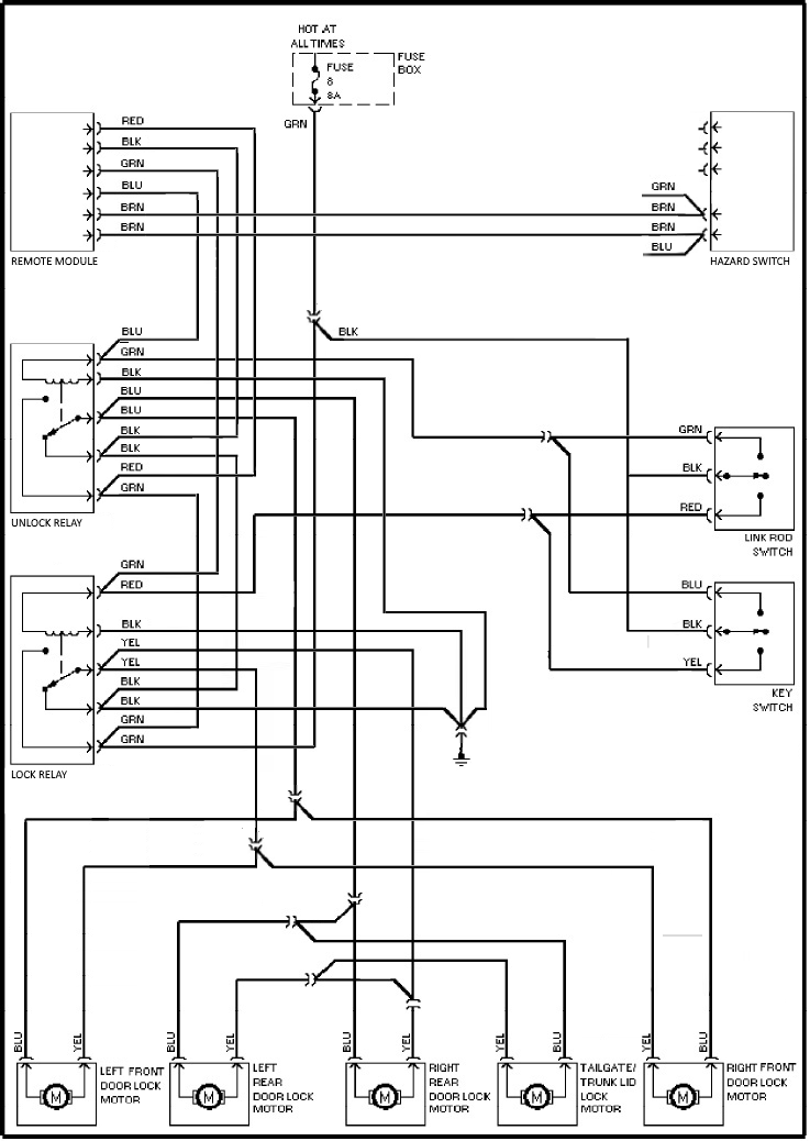
Pull your 386M out of the box. We will be working on the wiring harness first. You can remove most of the wiring from this harness. You will only need the Red, Black, Green, Blue and 2 x Brown wires, please refer to the diagrams below


I suggest making the red, black blue and green wires all the same length as these will all terminate at the relays, make the 2 brown wires longer as they will terminate at the hazard light switch.
Splice the red wire into the green wire on pin 87 of either relay (or you could add a male spade and insert it in the left over green female spade from step 2 if you wish)
Splice the black wire into one of the black ground wires at the relay base (or add an earth lug and run direct to ground)
Splice the green wire into the red wire on pin 85 of the lock relay.
Splice the blue wire into the green wire on Pin 85 of the unlock relay
Finally, at the back of the hazard light switch, splice one brown wire into the green wire and the other into the blue wire.

Remount your relays, plug in and mount the recever/central locking module (I found it sits neatly under the air vent directly on top of the lock and unlock relays), reinstall your dash components, instert fuse 8 and you are good to go.
Hope this helps.