• RWD
  • Volvo 360 b230 turbo swap

I am makin an instructional thread documenting the entire process of swapping a B230 turbo motor into the volvo 360 GLT.
I would appreciate it if you would NOT comment in this thread until it's complete, just to keep it neat and clean. Thanks! (feel free to follow process and comment on 'Alex's 360 build thread') :+1:


List of requirements!

Swap from 360 engine to b230 turbo engine:

Sump + dipstick tube
Oil pump
Distributor (optional but recommended as space is tight.)
Intermediate shaft (if swapping distributor)
Alternator + bracket
Engine mount brackets and engine mounts (if turbo oil return line is relocated...more on this later)
Water pump and pulley.
360 spirit and essence ?

Required engine components:
LH 2.4 compatible 60-2 dished flywheel
Mix and match clutch + pressure plate...
Wiring loom from LH2.4 vehicle, preferably later model 240, or custom made loom.
Use the b230 starter motor
B230 crank angle/position sensor. (You will need to make a custom mount, more on this later)

If fitting a front mount intercooler, you will need to remove the A/C condenser and drill/cut larger holes In the bulkhead/sheet metal next to the headlight to accommodate for the pipe work.

Exhaust - you will need to make a custom downpipe. If you have the skills and/or the money, a custom turbo back system is a win.

To be continued...


3 months later
360 sump to be swapped over to the b230 - note that the 360's sump bolts must be used as they are longer.


Because the sumps are different, you will need the 360's oil pump (right). Its longer than the b230 pump. Alternatively, you could possibly extend the length of the b230's pumps pick-up tube...


Prime the oil pump when installing by filling it with oil. Before you start the car, make sure you are getting oil pressure by disconnecting the ignition coil and turning the engine over with the starter motor. You can connect the 360's oil pressure sensor wire to the new sensor by swapping the spaded connector for a tubular connector. I removed the oil feed line to the turbo and waited for a nice flow of oil to come before I was confident it I had pressure. If you do this, make sure when you reconnect the oil feed line, you turn the engine over with the ignition coil still out for atleast 10 seconds to ensure the turbo is primed with oil. Your starter motor will become hot with extended use, be sure to let it cool down between cranking.
Intermediate shaft:

Check if the intermediate shaft in the b230 has the gear to drive the side mounted distributor, as some early b230's did have this. My b230et did, so i didn't need to remove it.

Simple to remove, especially if the engine is out. You will need to remove the oil pump gear which is under the PCV flame trap.


Simply remove the flame trap and use a magnet to pull the gear out.
The intermediate shaft requires the crank pulley/harmonic balancer to be removed and the intermediate shaft gear/pulley + the housing which holds the seals. If you make sure that the side mounted distributor and the oil pump gear is removed, the intermediate shaft should just slide out with a bit of encouragement.

I didnt take pics of this, but found some online:

Intermediate shaft comparison. Distributor gear and no distributor gear


The b230 will have the hole to fit the 360's distributor. You will need to remove the old blanking plug. Hold a screw driver or punch on the inside edge and tap it with a hammer. The plug will rotate and you just need to pull it out some pliers. Simple.
Installing the distributor is easy. I set the 360 engine to be at top dead centre and made a note of where the rotor button was positioned before removing. Then when installing into the b230, put the engine at top dead centre and place the distributor in the same position. Be sure to inspect and clean the bearing surface the distributor sits in as mine was gummed up and rusty, and lubricate with oil or assembly lube. - note that the EZK ICU will adjust ignition timing and as long as you have the distributor generally in the right place, it will be fine. Oh, and dont connect the vacuum advance for the distributor.


If you decide to remove the rear mounted distributor, you will need a bung to seal the hole in the head. @AshDVS sold me a kit with a plate to stop the bung/seal from comimg out in the event of excess crankcase pressure.

The 360's alternator and bracket is easy to adjust. Plus, I preferred the 360's alternator as its postion allowed for more contact of the belts over the water pump pulley. I dont think it matters that much as it runs two belts, but i preferred to use the 360's alternator and bracket as it doesnt really get in the way and free's up space on the intake side.
Note - You may notice that the 360's alternator position seems to put a slight twist in the belt path. This is strangely normal as of the three 360's I checked, they all had the slight twist in the belt caused by the pulleys on the alternator being positioned slightly closer to the front of the car. Also, you may notice the waterpump pulley appears to rub slightly on the timing cover. I lightly filed mine, but haven't noticed any issues with it hitting with the engine running.


Here's a photo of the b230 alternator and bracket in position.


Engine brackets and mounts:

Ok, so you will essentially need to make custom mounts. Classicswede @DaiBrace are now making engine mounts and brackets for the conversion. The points of impact are the turbo oil drain line on the engine bracket (the one that bolts to the chassis). I was able to get a flexible, braided oil return hose to gain further clearance, but even then it needed to be manipulated/slighly bent to clear the engine mount bracket. I also think the 360's engine mount itself may be very close to the oil return pipe or hose, even if you use a braided hose and flex it out of its path.
I bought some poly engine mounts from classicswede.co.uk - very stiff and a little vibration but worth it in my opinion.

If using the same set-up as I have, due to limited space, the turbo-side mount will need to be installed in one piece (chassis bracket + mount + 360 engine bracket) after you have craned the engine in place.


Braided oil return line from Mamba (ebay) with turbo oil feed line. I highly recommend the use of braided turbo lines.


Water pump:

You will need the b200 water pump on your b230 engine. Note that the b19e pump will not fit on the b230, they have a different bolt pattern. Dont just order a pump for the 360, make sure its the b200 pump.
Swap over the water pump pulley from your 360 as its shorter.

Pics of b19 bolt pattern (left) and b200 bolt pattern (right)


Difference between the b200 (left) and b230 (right) water pump in length. The b200 pump is 20mm shorter.


Difference between the volvo 360's water pump pulley and the b230's. The b230 pulley is about 15mm longer, which means by using the b200 pump and the 360's pulley you gain an additional 35mm of clearance over the b230's pump and pulley.


Flywheel:

Edit: ClassicSwede @DaiBrace now have a custom flywheel and clutch kit for this conversion.
Alternatively, you can use the dished flywheel from an LH2.4 car. It needs to have the 60-2 trigger wheel pattern.

I bought mine new from Skandix as I wasn't able to source one elsewhere.

Most Other flywheels wont work due to the limited space within the 360's bellhousing (citation needed), but it is possible to use the automatic flex plate (for trigger wheel) and get a custom flywheel to bolt on with the flex plate, but it will likely cost more than a new flywheel anyway.


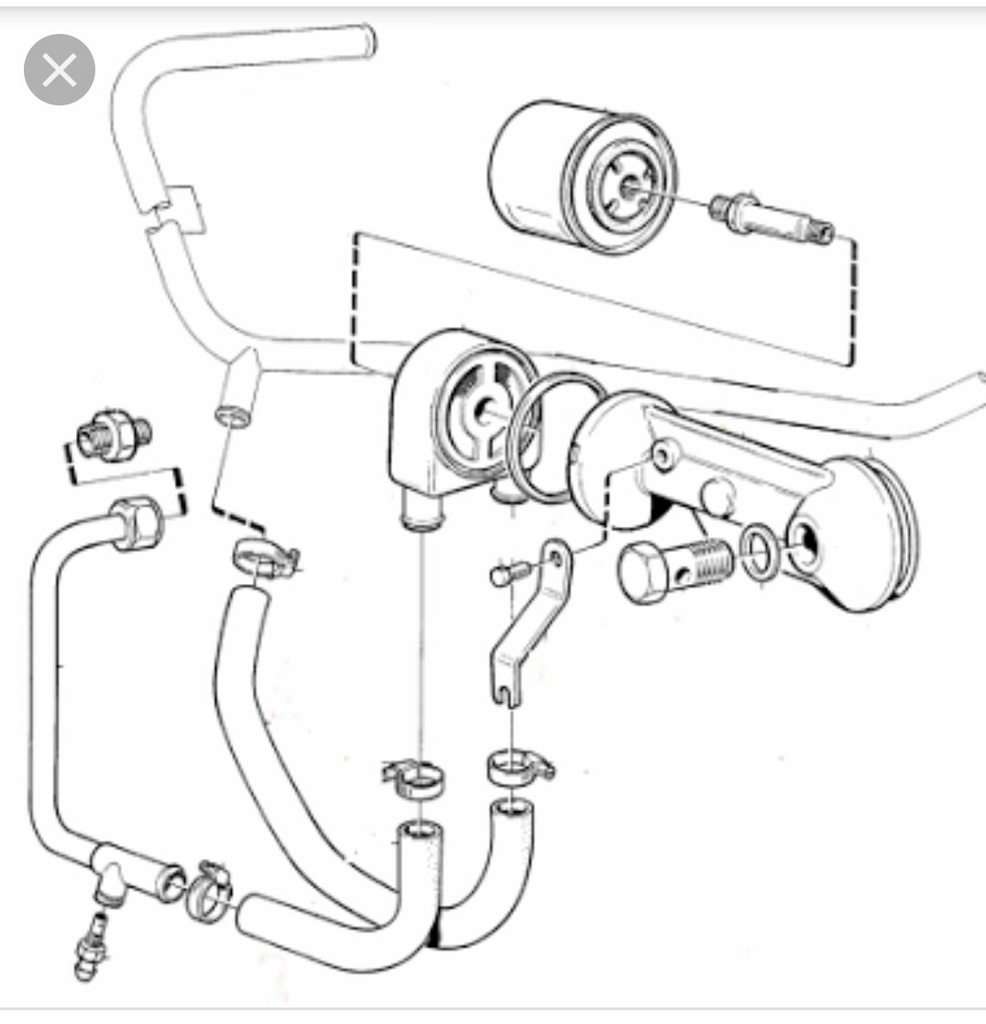
Pressure plate and Clutch disc:
You will need to use a 360 pilot/thrust bearing.

Dai from Classicswede.co.uk sells clutch kits for the turbo conversion. My next clutch ill be getting from him. Things to note is that Classic Swede offer a paddle clutch which has a thickness of 8mm and will require shims to prevent the clutch from slipping. Dai over at Classicswede also offers the shims for sale, but because the 360's bellhousing is tight already, you may need to grind off a small amount of the 360's bellhousing to prevent the pressure plate from making contact. This isnt a big deal and there is some info relating to the issue covered on this thread:

http://www.volvo300mania.com/uk/forum/viewtopic.php?f=6&t=8663&p=184410&hilit=228mm+clutch#p184410

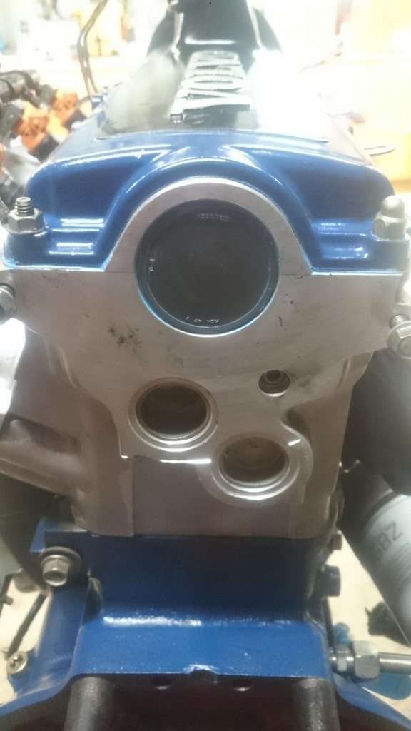
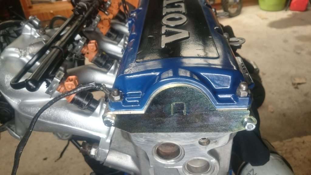
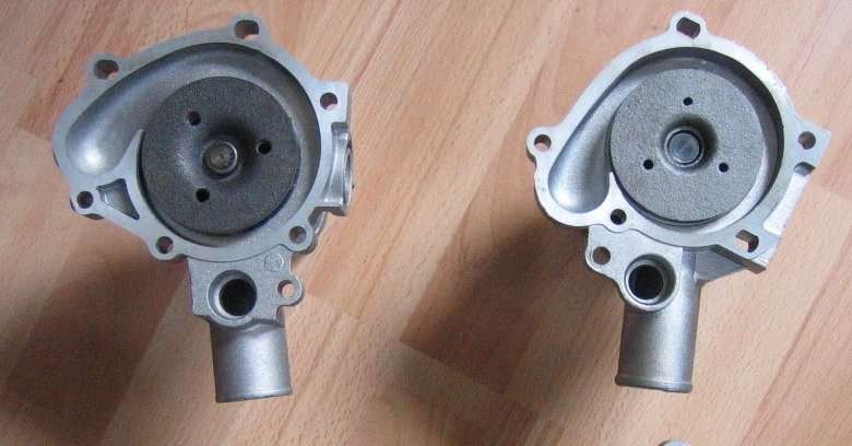
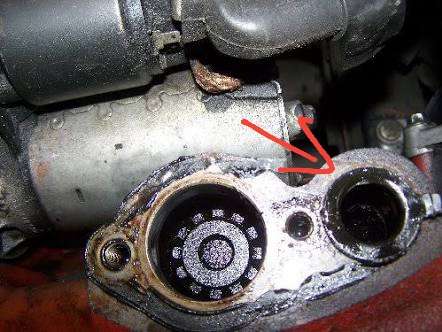
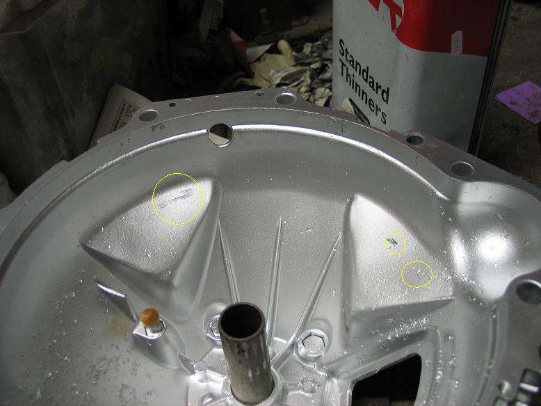
Pics of contact points from the pressure plate to the bellhousing:


If you dont get one from Classicswede then the below information will be very useful:

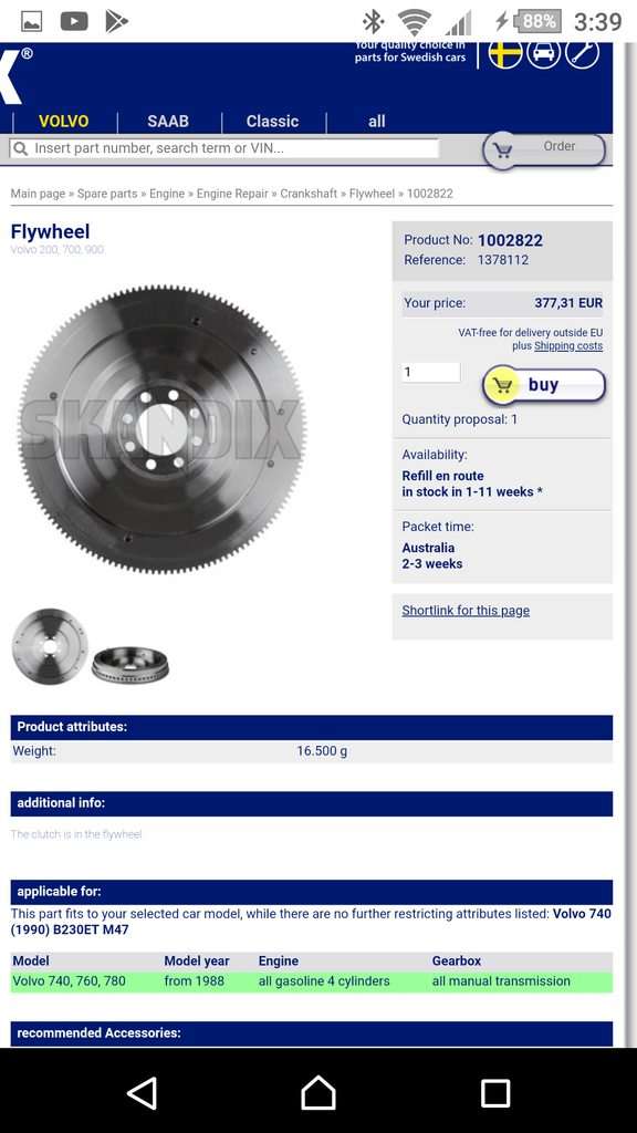
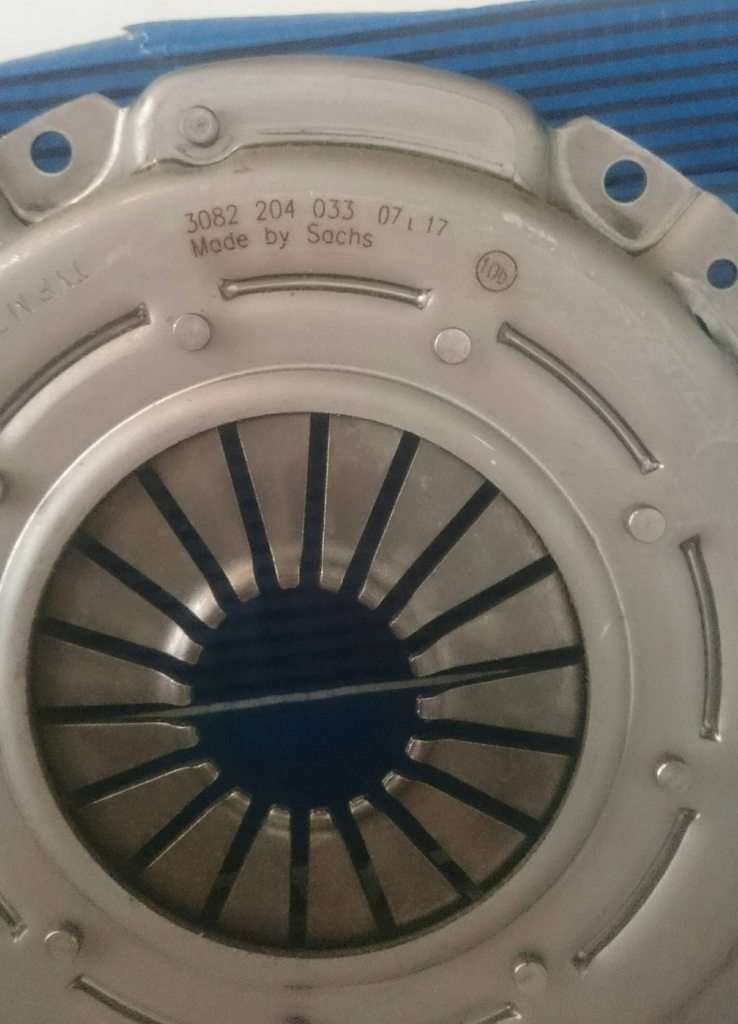
The turbo diesel pressre plate apparently has a higher torque rating than the other pressure plates suited for the dished flywheel, below are the part numbers it is associated with:
Sachs 3082 204 033
Also know under P/N 1209874

https://rover.ebay.com/rover/0/0/0?mpre=https%3A%2F%2Fwww.ebay.com%2Fulk%2Fitm%2F352234429717


The clutch used needs to meet the following specs:

Teeth: 24
Hub profile: 18.30x20.4 24N
Diameter: 228mm

I have been advised that the Vauxhall Astra gte 2l 16v use a Clutch disc which meets my requirements. Specifically one which uses the F20 transmission, which I believe were made between 1988-1991.
They are hard to find....thankfully, Ride_on from 300mania has helped me out with some info and told me that Helix Autosport do clutch kits for the Vauxhall Astra, so I gave them a call.


70-4627 organic plate £136.55
76-4627 (5) Paddle plate £166.23

Organic clutch pic:


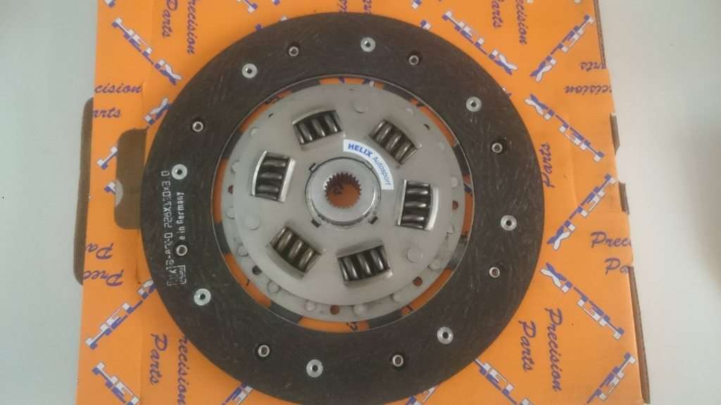
They also said they could do a 6 paddle plate clutch. I went with the organic clutch as it should be fine for my application. I think the above pressure plate and organic clutch will be good for about 400nm which is likely well beyond what I will be producing.

Clutch thickness is 7.6mm which apparently works fine. Any thicker and you require the use if shims between the flywheel and pressure plate...which may require some grinding of the inside of the bellhousing to accommodate. (See the start of this post)

This set-up works perfectly and I can report that it doesnt slip and operates smoothly.

CAUTION: Be sure the new clutch slides freely on the input shaft before installing on the engine. Dont make the mistake I did unless you just love pulling engines out and installing them again. A 2 minute check can save you from premature hair loss.

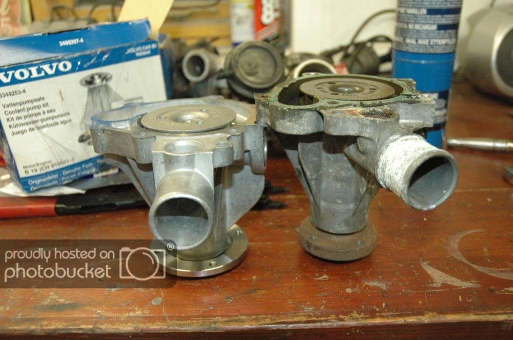
VOLVO 360 RELEASE BEARING: You will soon find out that the clutch release bearing for the 360 has been discontinued...
The volvo 940 with the M90 transmission has a similar release bearing, only it's shorter. For reference it's Sachs P/n 3151 189 031.


This is the original:


I was told that it can be used instead of the 360's release bearing, but will need to put a 3mm spacer between the bellhousing and the clutch fork pivot ball. This likely would've worked, however, when I tried installing the 940's release bearing it wouldn't grab onto the 360's clutch fork because it was too narrow in the neck.

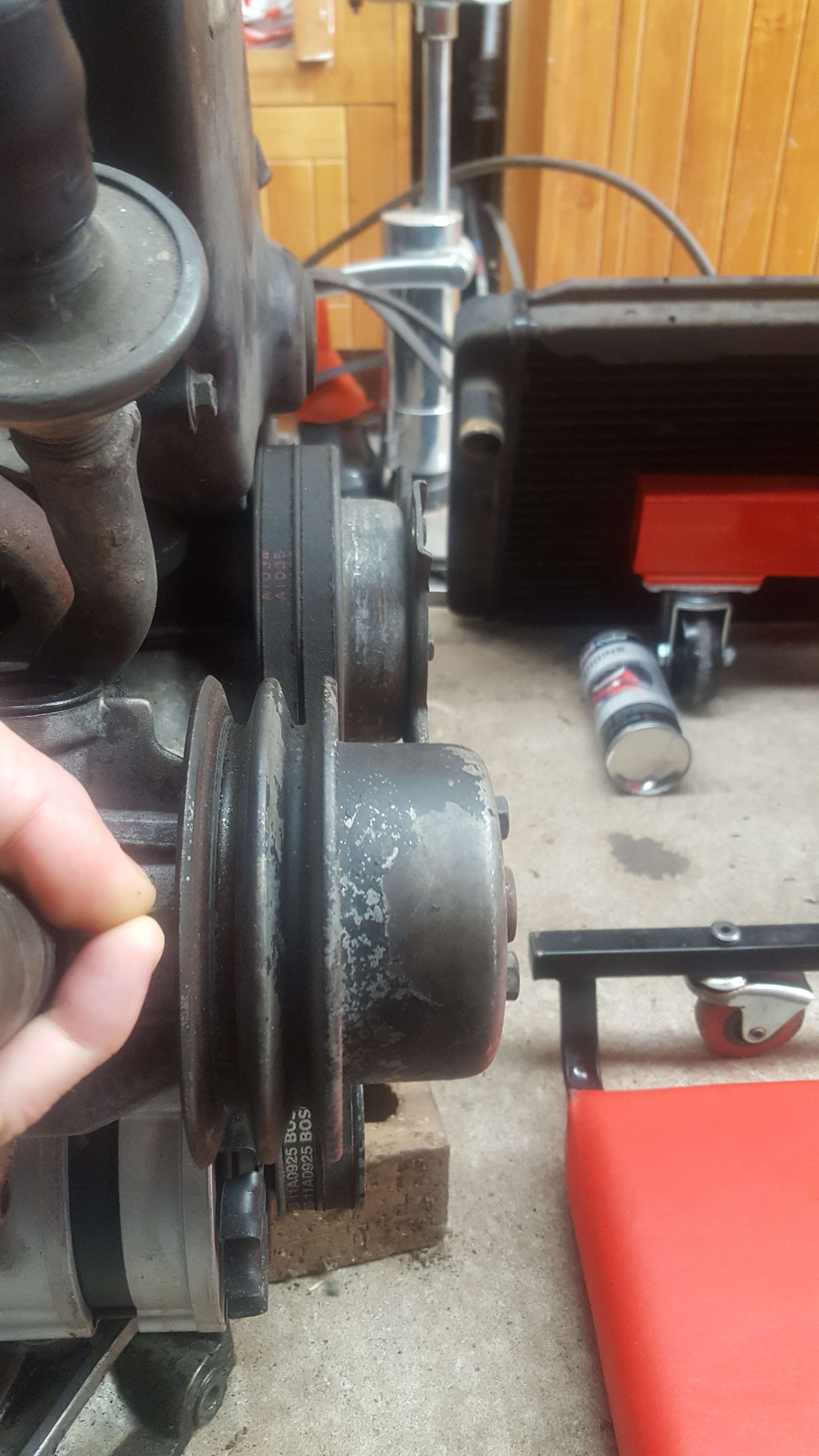
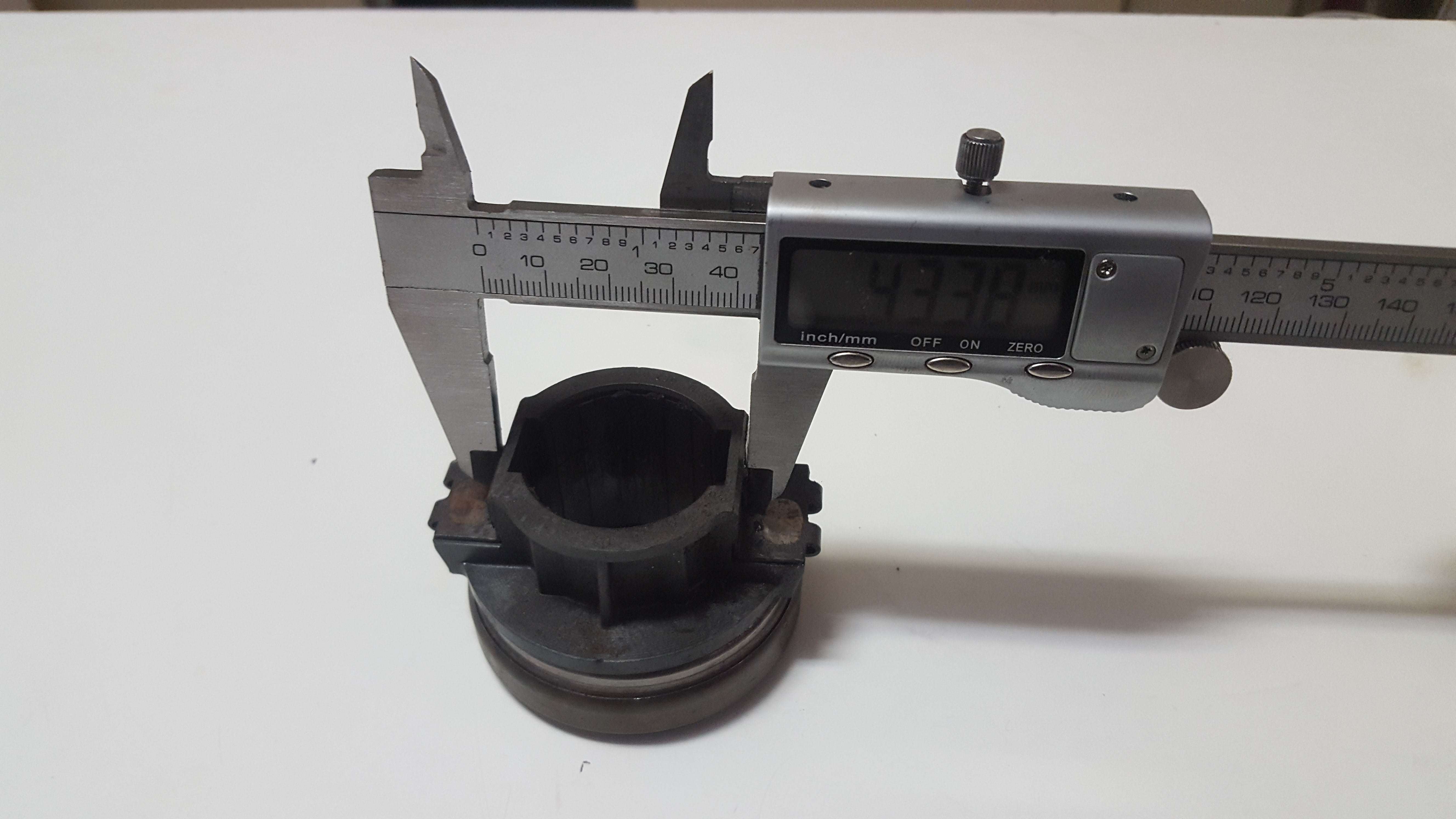
360's release bearing - neck width is 43.38mm


940's release bearing neck width


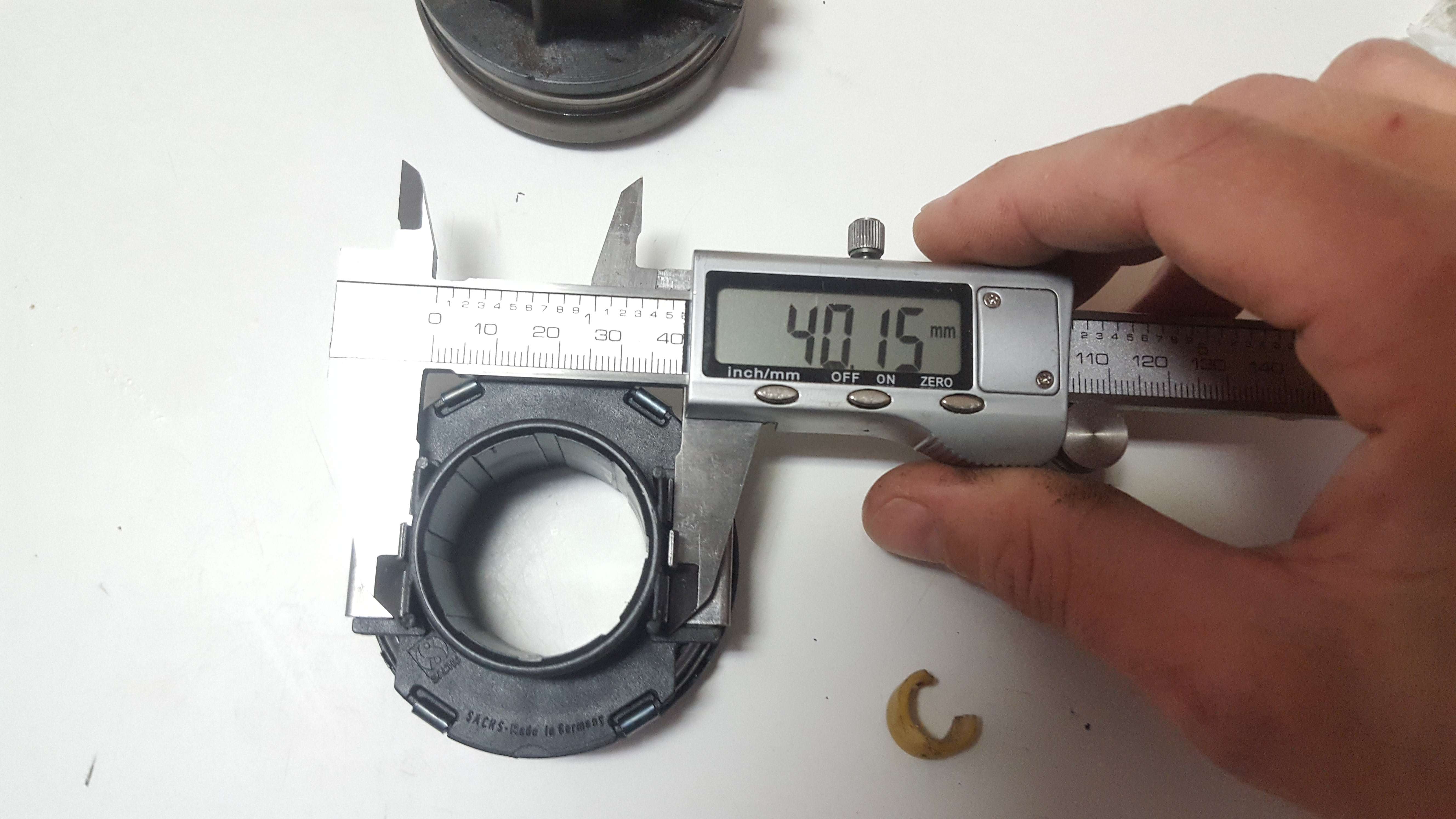
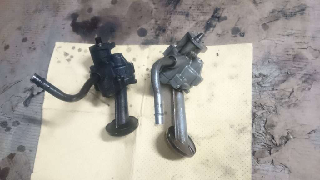
360 (bottom) vs 940 bearing


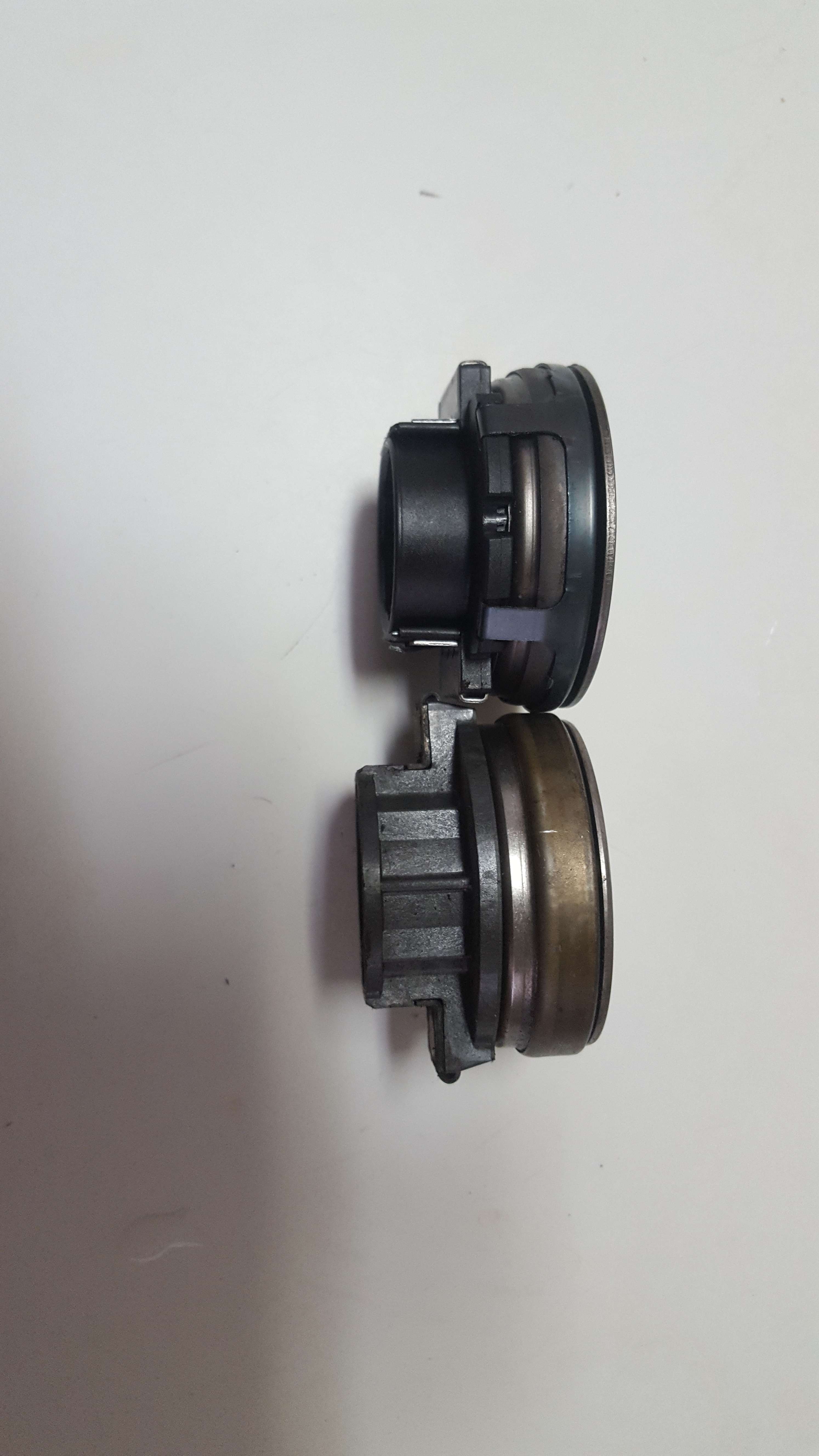
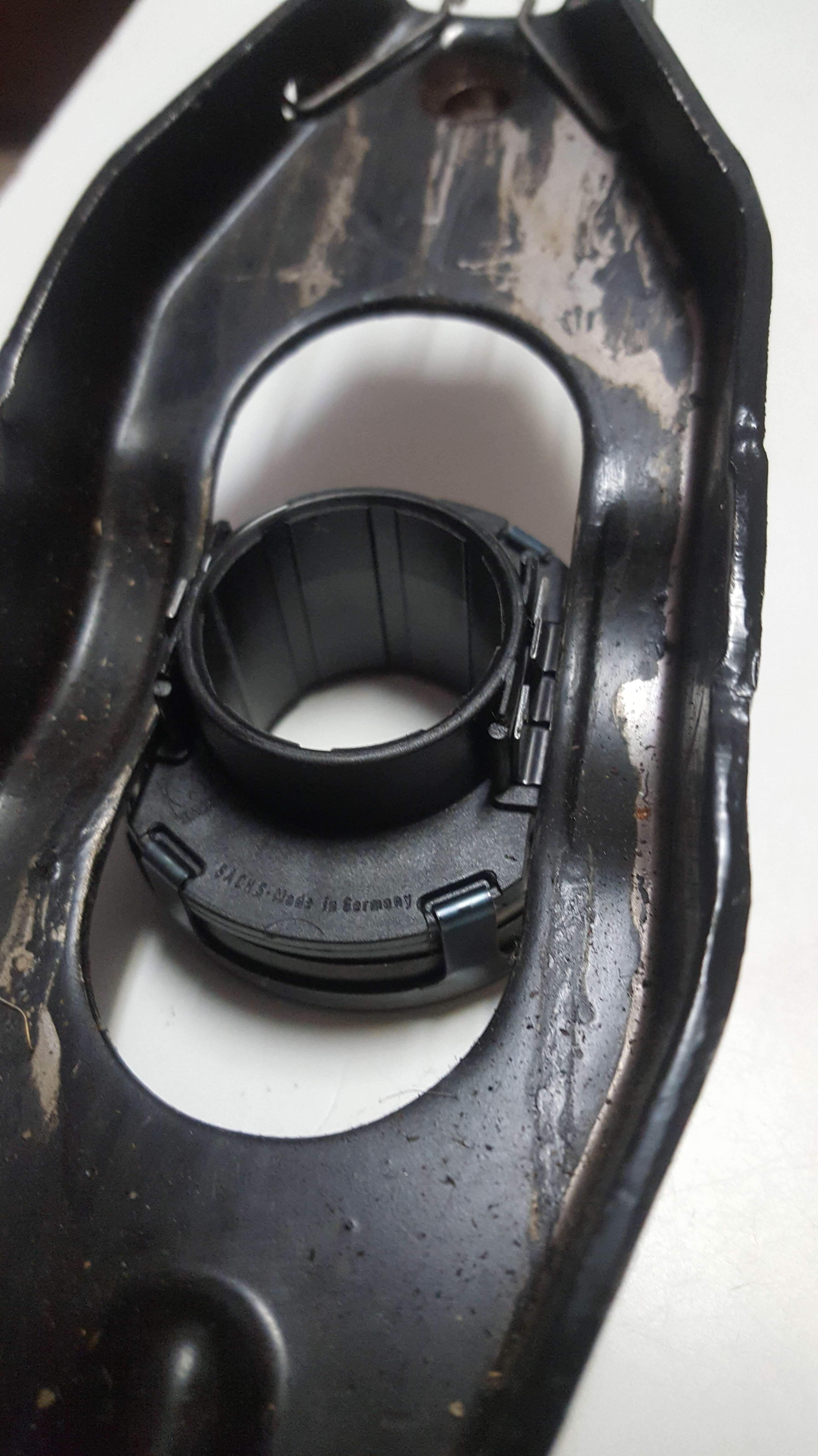
360 bearing in clutch fork - nice and snug


940's release bearing in clutch fork - wont grab


You could bend the tabs on the 940's release bearing to make it fit, but its not ideal.


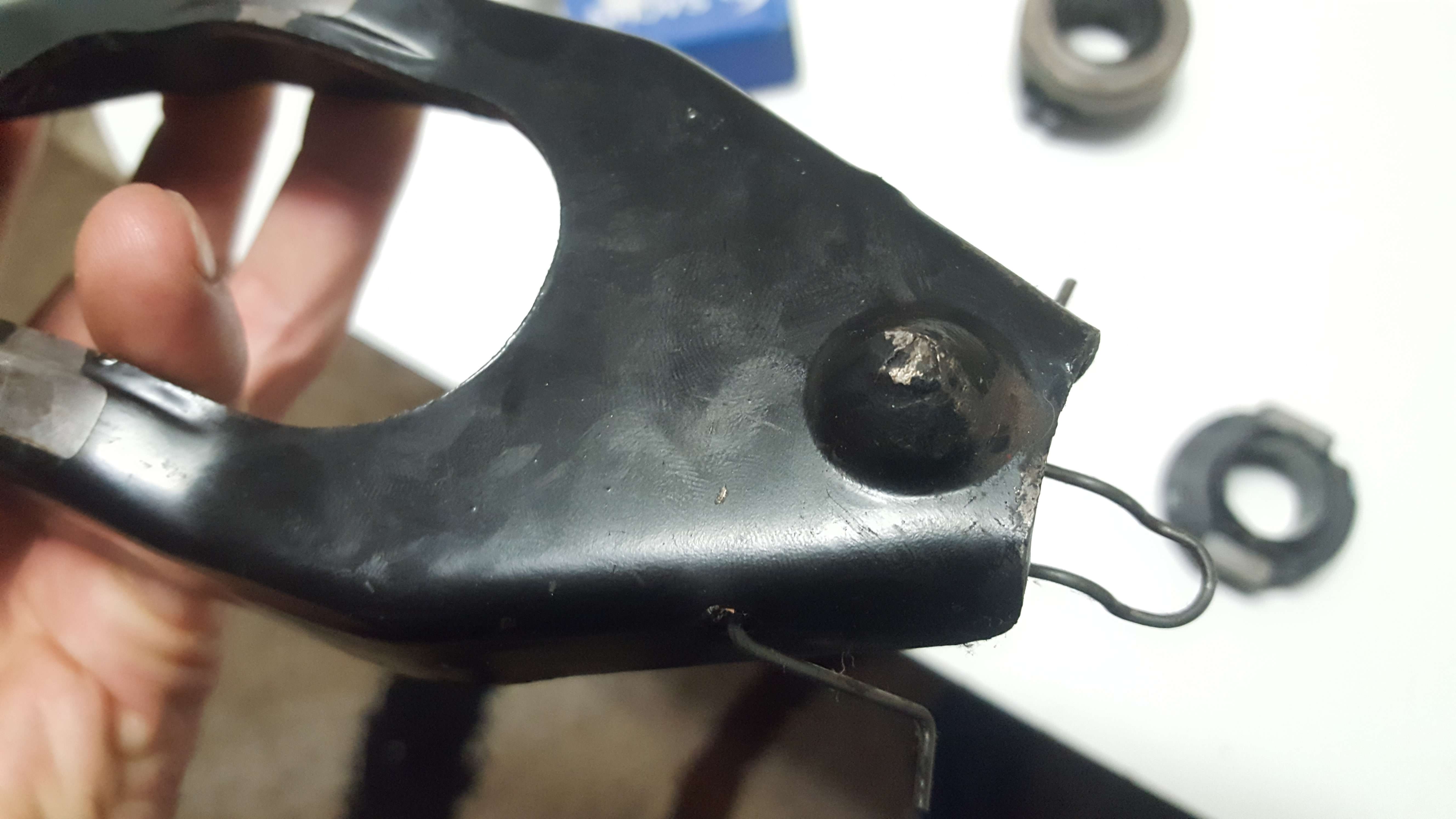
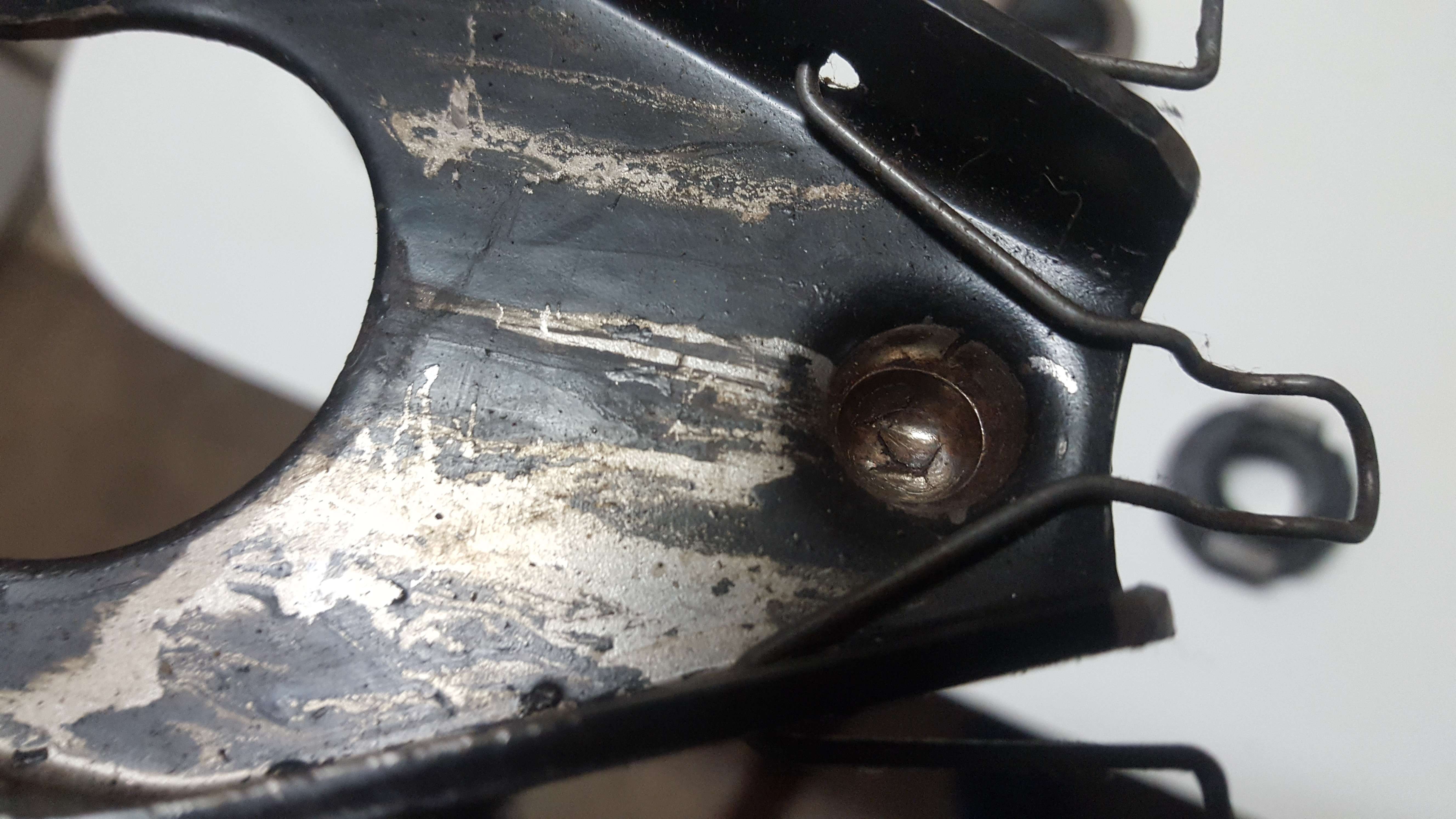
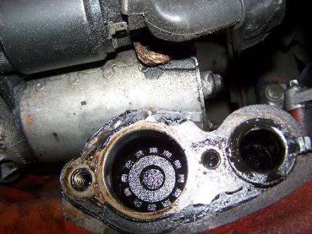
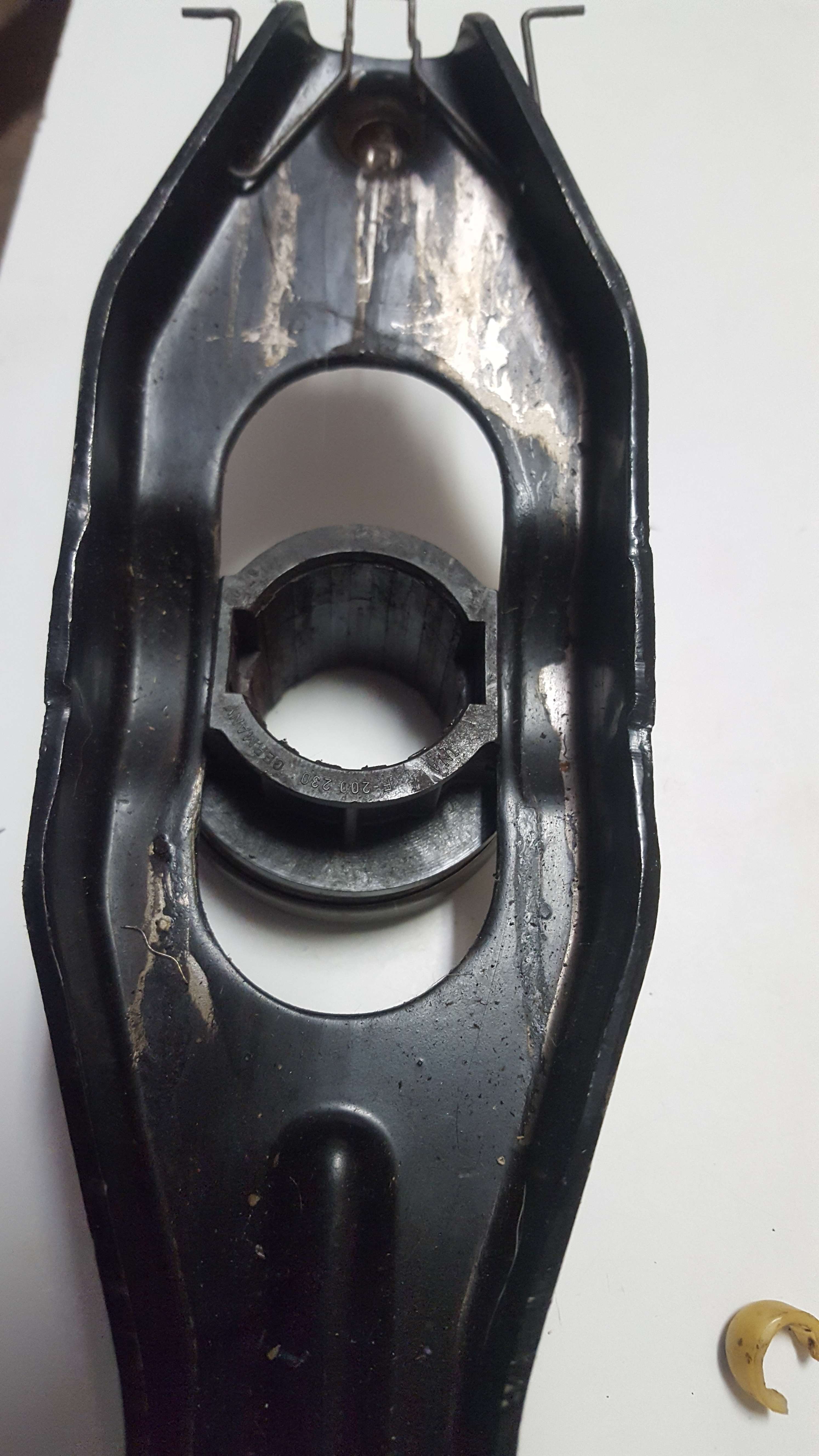
Also, the factory pivot ball on the 360 has a nylon cap. My donor car's pivot ball had a disintegrated nylon cap causing serious metal fatigue on the clutch-fork-pivot-ball-socket <---(try say that really fast 5 times!), to the point where the pivot ball had almost worn through the clutch fork completely. This is worth checking and replacing if you are doing anything clutch related.


Metal fatigue on clutch-fork-pivot-ball-socket


Wiring loom:

I bought a new loom from Classicswede.co.uk
Its a great loom and will save you a lot of headache. The loom from Classicswede is based on the later model 240 loom, so it is best to get one of those if you dont want to splurge on a new loom.

The 740 and 940's loom is intergrated with the rest of the 940's or 740's wiring and is nothing short of a nightmare to pull out, let alone sort out. The 940 is the worst of the two to deal with. It's like a bowl of spaghetti meets a NASA space shuttle.
Exhibit A) - 940 intergrated loom:


Pic of new loom from Classicswede.

Note: if using this loom you will need to use orange top or white injectors from the 850 t5 or v70 t5.


Additional info:
If using the loom from Classicswede (this may apply to the standard later model LH2.4 240 loom of which Classic Swede's loom is built from) there is a section about connecting the fuel pump power wire, which was a bit confusing.
Here's a page (page 4) from the instructions which Dai emailed me for the loom:


Note that the harness connection B2, which has a Red/Yellow (fat) wire for the fuel pump, needs to be connected to the engine bay fuse behind the battery...which is this little bugger:


For your tacho to work, you need to connect the black wire from the 360's harness (not engine loom, this is the body loom which stays with the car) to the negative terminal on the ignition coil (terminals with the number 1 next to it, the terminals with number 15 is +positive). There is a black and green wire, only the black needs to be connected.


For your coolant gauge to work, swap the 360's temp sensor (one with spade terminal) and connect the yellow wire from the 360's body loom. The wire(s) will be obvious as they are positioned in the right area to fit.


As mentioned above in the Oil pump section, you can connect the oil pressure sensor wire from the 360's body loom (near front right headlight) by removing the spade terminal and swapping it for a tubular socket type terminal.
Starter motor:
Just use the b230 starter motor. Its a tight fit with the 360's dipstick tube in the way and i would suggest you install it just before you slide the input shaft into the clutch spline the whole way, so you have a bit of wiggle room to slip it in. There's a blue and white (it may be blue and yellow) wire from your 360's body loom which will need to be connected to the spade terminal on the starter motor. I believe this comes from your ignition switch(?).
Crank position sensor:

You will either need to cut the bellhousing of the 360 to accommodate the CPS's bracket (which was the 940 donor car i used) or make a custom bracket, which is what i did. Keep in mind that the distance the magnet on the CPS needs to be away from the flywheel is very small. Essentially its 1mm +/- 0.5mm - so a range from 0.5mm - 1.5mm.
If you make your own bracket, once the CPS is set, rotate the crank by hand first to make sure the CPS is not hitting the flywheel.

The 360's bellhousing has bolt holes surrounding the CPS hole. Mine weren't threaded so it required me to tap threads into the holes. Do this before you install the engine as it is easier to clean up, or just be careful.

Here's a pic of what I did. Its not the most beautiful thing, but it works well. I drilled holes in the sides of some 20x20mm squared bar, cut out a middle section, drilled a hole in the bottom to run a bolt through and uses some spacers to achieve the desired height. If you can, weld the bolt to the bracket so you dont have to use a spanner as theres not much room between the bracket and the bellhousing.

Front mount intercooler:

Ok, lots of info in this part. Sourcing the right intercooler will save you a lot of headache. There is very little space to work with and an the intercooler ports (inlet and outlet) need to be in the correct location.

This is the one I used and it was perfect. You dont want depth to be much greater than 65mm or your grill wont fit on. You can definitely use a taller intercooler, but the ports need to be in the right location.


You need to widen the holes in the bulkhead to accomodate the intercooler piping. I used a dremel with a tungsten carbide grinding tip, which made light work of it. I also placed some protective edging to make sure the intercooler hoses were safe and sound:


SPACE IS TIGHT!


You will need to make up some brackets to hold the intercooler. This wasnt very difficult, but you need to take some time to get it fitting right.
I used the upper radiator brackets to hold the intercooler in place and made up a lower bracket which bolted onto the from bumper support (I also put in some rubber grommets between the bracket and the intercooler to absorb shock).


HOSES + PIPING:

here's what I ordered:

3x 2.5" to 2.25 inch 90 degree silicone reducers (two for the intercooler and one for the throttle body)

Turbo side:
1x 2" 180 degree bend (from turbo)
1x 2" straight joiner pipe
1x 2" to 2.25" straight joiner hose


1x 2.25" 90 degree intercooler pipe. I needed to cut this down to fit and welded 3 beads on the ends to keep the hoses from slipping off, this is the piece I ordered to do the job:


The intake side is simple. Using the old intercooler piping (mine was from a 940 turbo) you just need to make 2 cuts on the old pipe and join it with a 2.25" joiner. Make sure you put the port for the Idle air control valve (IACV) in the right location and either weld a few beads around the tips of the pipe to stop the hoses coming off or get the ends rolled wider from a shop that can do the work. I welded beads on mine as the hoses were hard to get on even with a straight pipe.


Downpipe:

You will be taking some time with this. I cant offer much advice except get some off-cuts with bends from an exhaust shop. From memory the outside diameter of the original downpipe is 60mm, so ask an exhaust shop to make a reducer piece from 60mm to 50mm and you can then weld it to the existing exhaust where it bolts to the exhaust support bracket...or join it further down the line and weld a nut onto the downpipe to connect it to the support bracket. Doesn't make sense? You'll know what i mean when you tackle the job.


I borrowed this pic from 300mania


This thread from ride_on (Tony) at 300mania helped me a lot, I actually borrowed the intercooler and piping idea from him and I honestly dont think I would've had the confidence to take on such a swap if it weren't for him and his thread. He has saved me a massive amount of time by sharing his knowledge and is actually the inspiration behind this thread.

http://www.volvo300mania.com/uk/forum/viewtopic.php?f=52&t=15882&hilit=Saloon+tidy+up&start=30


SPEED SENSOR:
LH2.4 requires a signal from the speed sensor as its "Used to adjust idle speed during engine braking and for constant idle speed compensation".

The 940 gets its speed signal from a sensor in the diff. The 360 transaxle has no provisions for this sensor to be installed...
Thankfully, ride-on from 300 mania came up with a solution:
by installing a cluster mounted bracket which is found in the 440's, which mounts a 'hall sensor' and an 'axial resistor'. He 3d printed his and has saved a public 3d printing file here:
https://www.tinkercad.com/things/d7KWyZdxanN-vehicle-speedo-speed-sensor-holder-1980s-vw-volvo

Link to the thread:
http://www.volvo300mania.com/uk/forum/viewtopic.php?f=56&t=16514

For your convenience I have put most of the information below:

Parts required:

1 x 2k7 1/4 axial resistor
2 x No.2 x 9.5mm self tapper screw
1 x A3144E through hole hall switch
10mm x small heat shrink
3 x 7cm small gauge wire
1 x 3D printed holder
Pea of epoxy glue

The hall sensors are so small and you need to solder the axial resistor onto the two outer prongs and wire onto all 3 prongs. I destroyed two already by overheating the hall sensor. I had to get some high flux solder (60/40 tin and lead) to do this one.


Instructions from Tony at 300mania:
1. Form the hall sensor by widening out the legs a little and bending the plastic part at 45 degrees to the legs, the widest part should face out (down)
2. Form the resistor to attach to the outer 2 legs and to be bend back on itself
3. Pre-tin the resistor and sensor legs then solder, use a croc clip + tweezers jig to hold (will add photos later)
4. Strip and solder the wire to the legs, don't linger or you'll melt the resistor off
5. Put the heat shrink on the middle leg and slide up close to the hall sensor, heat to shrink (without melting the solder)
6. Fit the lot into the holder and bend the hall sensor 90 degrees, bend the resistor down flush with the holder.
7. Glue the hall sensor and wires with epoxy at both ends and the resistor, use minimal amounts to ensure the epoxy does not protrude too far. Arrange something to hold it in place while the epoxy hardens, or consider super glue initially.

:::::::::::::::::::::::::::Additional info::::::::::::::::::::::::

Apparantely the neutral/park position switch needs to be earthed to achieve a steady idle. Just remove the back cover from the LH2.4 ecu connector and trace the wire for pin 30 for the neutral/park position switch and pin 14(and 15?) For the Aircon and run those wires to earth. I just grounded mine on the firewall inside the cabin. In fact, the loom I bought from Dai at Classic Swede had the cables for the A/C running out an 8 pin connector plug near the ecu, so it was very convenient.

LH2.4 and EZK Pinouts:

http://ipdown.net/jetronic.info/tiki-index.php?page=LH2.4+Pinouts+and+Diagrams

Ozvolvo link (thanks James!):
https://ozvolvo.org/discussion/9733/bosch-lh-jetronic-2-4-ecu-and-ezk-pinout-tables#latest
Get yourself a turbo heat blanket or make up a heatshield. The one I used was for a t3 turbocharger. Oh, and wrap your downpipe with heat wrap before your brake fluid evaporates ?


Radiator hoses + overflow bottle hoses:

You will need to use the 940 turbo's radiator hose (bottom hose) and hose from the overflow bottle as they provide coolant to the turbo. Some cutting and joining is required, but this is quite simple to do, and even easier with hose cutters. The braided coolant lines i used were very helpful when joining them to the hoses as you could move them around.

Note: I used the 13c turbo from the 1992 940 se
Other things to note:

The exhaust manifolds are prone to cracking. Mine was a 90+ manifold and it had multiple cracks on the underside. Its cast iron and they're not easy to weld. Cast iron needs to pre-heated and slowly allowed to cool down to make an effective weld (and I think you need to use nickel welding rods?).

Get a professional to do the job or you'll find that the welds will crack again.


It's worth mentioning the oil drain hose which goes from the PCV oil seperator/flame trap to the sump.

Stealthfti has covered this on the turbobricks forum:

The advice from Stealthfti is this:

"Don't bother replacing it. Just use the top 1/2in or so to act as the seal for that side of the separator box to the block, or use an O ring.
I do not re-install those return tubes. They are there to supposedly reduce oil spray or foaming in the pan. All they really do is impede crankcase ventilation. AND, in a worst case scenario on a high mileage motor with excessive blowby, that drainback tube actually allows oil to be pushed up into the separator box, and on into the vent hose...and on into the intake tract.

That drainback tube is not needed. Save yourself some grief in the future: do not re-install one into your motor."


Heater hoses:
If you have the oil cooler which runs off the oil filter housing like this:


Then you will need to find a way to connect the new pipe to the heater core hoses, as the b230 one is longer. Ride_on put in a 180 degree hose bend with a 90 degree joiner. Looks nice and neat


If you dont have that style cooler, you can just use the cooling pipe from the 360 and it will connect right up to the heater hoses as normal.