I've had a stuck power mirror for a while now, and while there are guides on how to pull apart the later-style power mirrors, I've not found anything about the early style, and fear of breaking it entirely has kept me from tearing it down... until now.
ContentsBackstoryComponent overviewMirror glass removalMethod of operation (explanation of motor drive and rigging assembly)Motor drive teardownElectrical guide + electrical debugging tipsHinge separationNotes on reassemblyRebuilding power mirror control switches (separate comment: see here)
I bought a spare pair of power mirrors from @Anthony_Demol58 recently and these have had their wiring harnesses cut quite close to the mirror housing.
Top tip: if you're pulling a car apart and don't have the time or willpower to disconnect sub-harnesses at their connectors, never never never cut wires close to plugs or flanges. To repair the harnesses later you will want at least 50mm of clearance from any plugs or fittings, and then an additional 20mm for each wire in the harness, so that solder joints can be staggered properly. As a general rule, cut the harness as far away from plugs and obstructions as you possibly can.
So given this situation with the harness and a desire to find out how to tear the mirrors down without breaking them, I decided I'd risk it on one of these spares and worst-case scenario maybe I'd have a way to safely repair the broken one. Good news! I figured everything out.
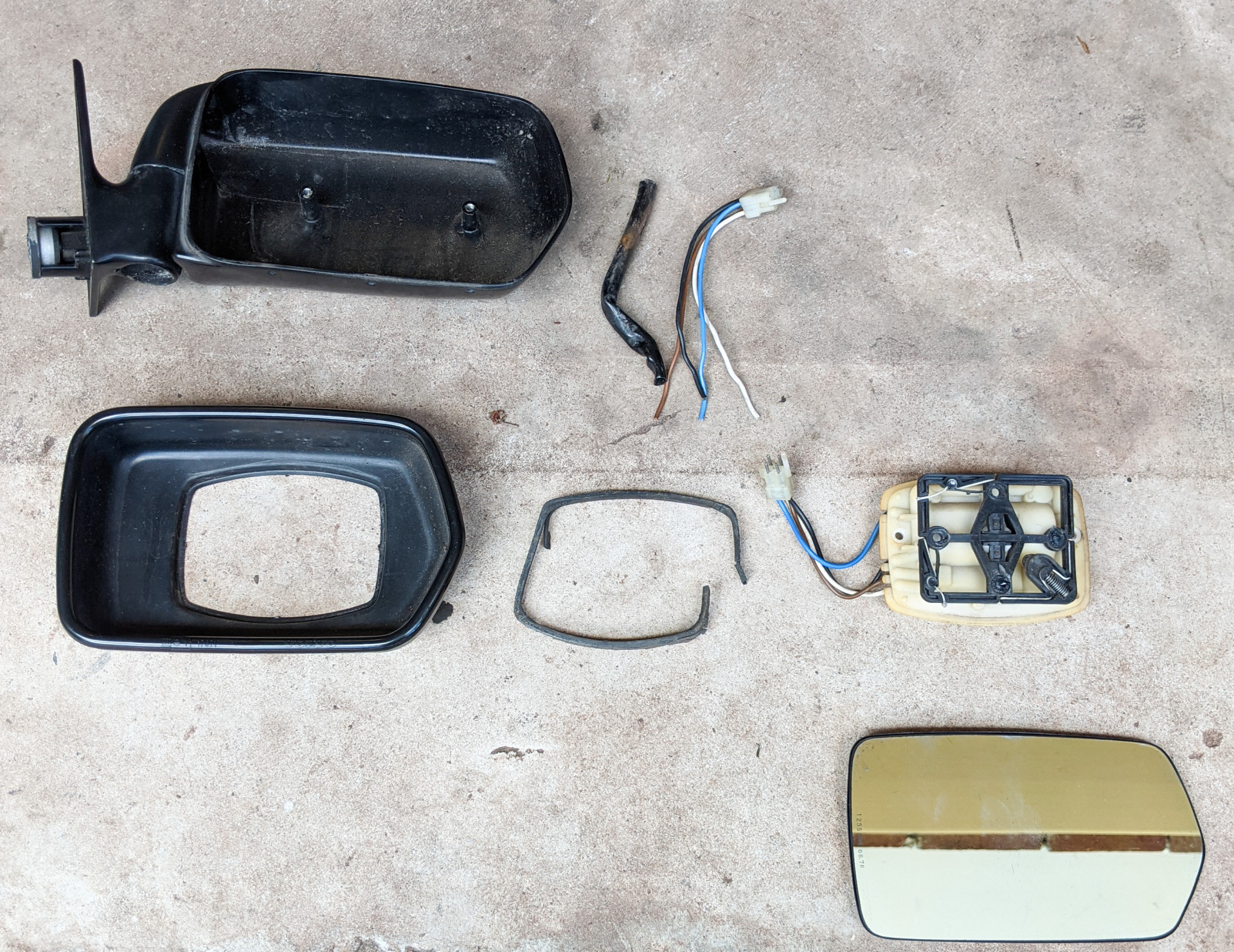
Component overviewTop row: rear housing, cabin wiring sub-harness (snipped)Middle row: front housing, motor gasket, motor and pulley frame assemblyBottom row: mirror glass
Glass removal
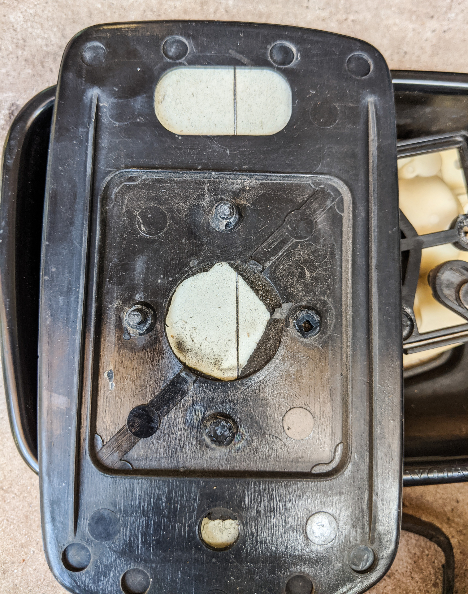
The glass is held to the pulley assembly by four plastic pins that form a slight interference fit into the housing. These pins will almost certainly be quite stuck. In this teardown I broke two pins and managed to avoid breaking the other two. My advice would be to get in behind the glass with some WD40 to lubricate those pins. To remove the glass, you will need to slowly work it up and away from the pulley frame. You can see the four pins on the back of the mirror in the following photo.
Method of operation
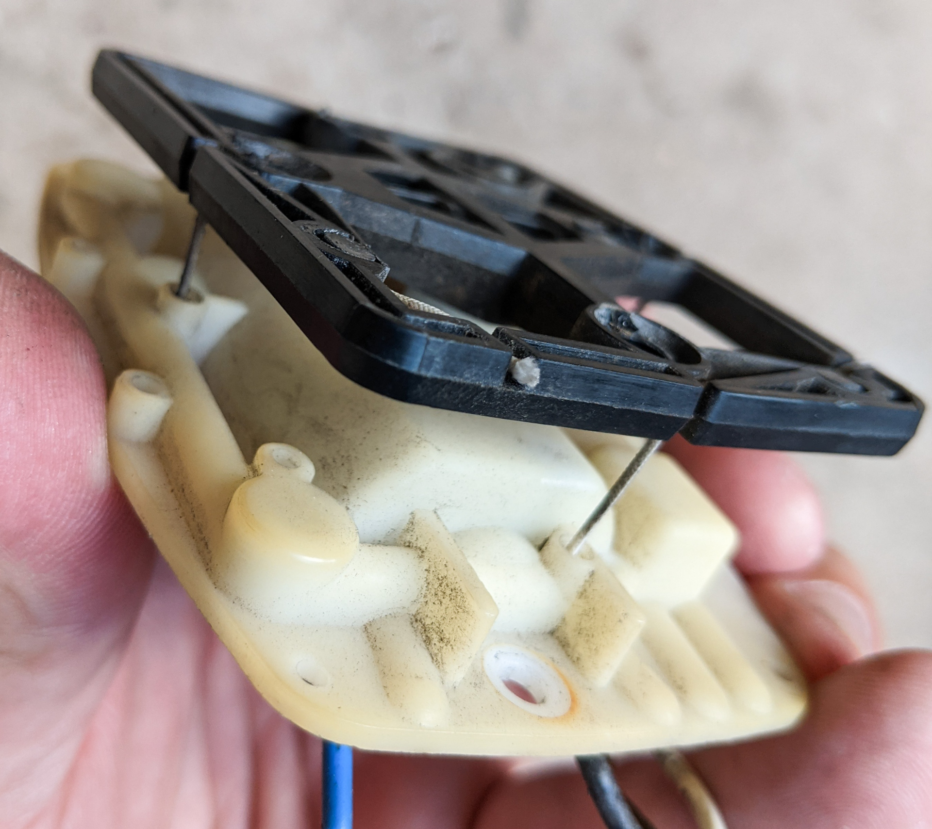
The motor and pulley assembly contains a motor, a solenoid, and a planetary gearset with a clutch driven by the solenoid. In this configuration and by reversing polarity to the motor, the mirror can be driven up-and-down or left-and-right. The output drives two strings that are wound into the pulley frame and held under slight tension by a spring tensioner (you can see this in the bottom right of the assembly). If you've ever tried to pinout the adjustment switches and found the wiring to be confusing, I think seeing the inside of the motor assembly will immediately make clear how this all works!
String drive view
Assembly overview
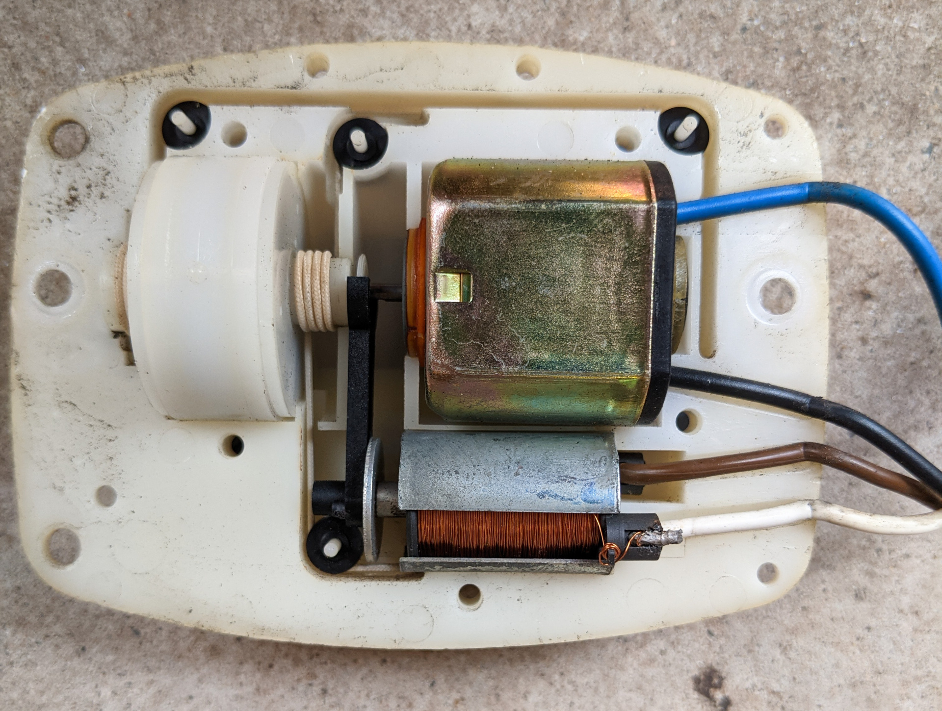
You can see the clutch in the middle, the black connecting rod captures a small splined shaft which can slide in and out of the planetary gearset (the white cylinder on the left) to drive either the left-hand string spool (just visible in this photo) which drives left-right motion of the glass, or the right-hand string spool which drives up/down motion of the glass.
The following short clip shows the clutch in action.
https://youtu.be/nz5RbwIDbQo
Motor drive teardown
The motor and pulley housing (above) can be separated with a small flat-head screwdriver. Work your way carefully around the edge, slowly separating the two halves of the casing. You do not need to remove the string, and the housing is not sealed or otherwise glued together. Given how clean the internals were after 35+ years of use, it seems that the close fit and external gasket do a good job of keeping it clean. I used some compressed air to blow out a small amount of debris but otherwise this all was in good working order.
My advice would be to avoid removing the string if possible as it will be quite difficult to set it up again correctly. If you're used to delicate work you may find this something you can do yourself.
One thing I didn't do was teardown the planetary gearset. This is because to do so would require detaching the tensioned strings that drive everything, and I'm pretty sure there is nothing serviceable inside the planetary. In another few decades maybe we'll come back to this and make fresh gears from scratch ?
Testing the other, broken mirror that I want to repair, I can see that there is a short across the solenoid coil. Luckily, the solenoid is easily removed! It just pops right out and if you are careful you should be able to tear it down and rewind the coil and restore it completely.
Electrical guide
If you aren't sure why your mirror isn't moving, you should start by testing the electrical circuits, before pulling anything apart.
Specs are as follows:
Motor circuit (blue and black wires): 30ΩSolenoid circuit (white and brown wires): 60Ω
If either of these circuits displays open circuit, you have an electrical issue. If either circuit displays zero resistance, you have a short-circuit. Test again from the sub-harness connector in the door and if you still see these readings you will have to pull the mirror apart to debug any further.
Mirror movement guide (for a right-hand mirror, left-hand mirror may be identical or horizontally mirrored from these pinouts):
+12V to blue wire, ground on black wire, white and brown wires disconnected: mirror points left+12V to black wire, ground on blue wire, white and brown wires disconnected: mirror points right+12V to blue wire and white wire, ground on black wire and brown wire: mirror points up+12V to black wire and brown wire, ground on blue wire and white wire: mirror points downHinge teardown
Requested by {"mention":{"name":"carnut222","userID":1611}}
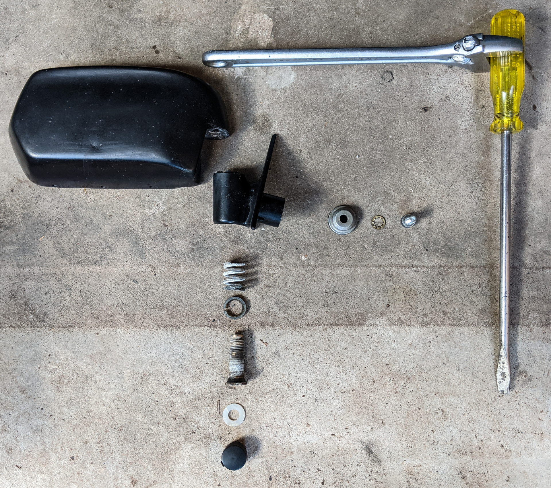
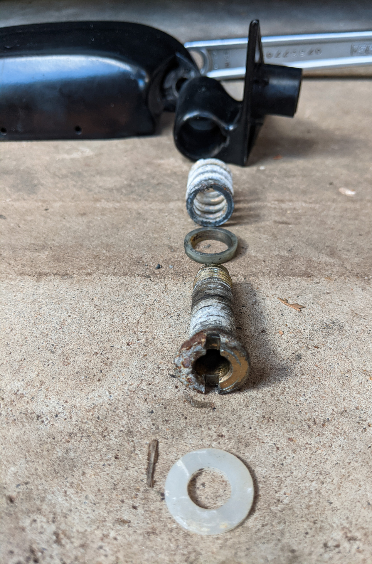
The hinge and mirror body can in fact be separated. If you are looking for more stuff to add to that bulk-zinc-plating order you're about to put through, you just found it! We have the body side of the hinge, and the mirror side, and there are three detents cast into the housing that locate the mirror correctly in the unfolded position. A plastic bushing and spring tension the assembly so that with some force the mirror can be folded in. Note that in my testing there is no limit to how far the mirror can be folded, but even though there are three detents, it will not "click" into the folded position as you might expect, as it will interfere with the car body before moving far enough.
Start by removing the plastic cap on the bottom of the mirror hinge. Once removed, you will see the wiring loom and a plastic washer. Unfortunately to really do this you need to first remove the wiring assembly, which will require unpicking the pins from the connectors and then sliding it all out. Not a big deal but if you've not worked with these connectors before there's a good chance you'll damage a pin, so consider yourself warned ?
Once the loom is out of the way, you can remove the plastic washer that covers the hollow screw head.
The screw can be removed by applying WD40 liberally, holding the assembly between your legs (I tried clamping it with the vice but it wasn't possible with the vice I have), and using a very large flathead screwdriver (and a shifter for leverage) to turn the screw.
Reassembly notesIf the gasket that separates the rear internal void of the mirror housing (where the wiring harness is) has perished, as it has on this unit, I think using silicone RTV sealant will be just fine. The motor assembly is held in by two screws (not pictured) and no adhesive is required.If you broke some locating pins on the mirror when removing it, you have a few options. If you want to just go full send, clean everything with alcohol and use a really good epoxy to set it in place. Otherwise, you can use a good quality double-sided foam tape. 3M make some nice tapes designed for attaching badges to cars, I'd use one of those as they are strong, heat-tolerant, and last for many years. Make sure all your surfaces are very clean. You may also have success popping the bottom of the snapped pins out from behind with a tiny pair of side-cutters, and you could then superglue those back to the frame, assuming they broke away cleanly.If you need to repair the wiring harness, the female bullet connector pins in the factory plug are a bit of a pain to get in this size and you probably don't own the right crimper for them, I would just replace the whole connector with a modern connector. There is a fairly generous amount of space in the rear half of the housing so you should be able to fit something.Was this guide helpful?
Consider supporting Oz Volvo if you don't already, by donating via PayPal. Any amount helps!