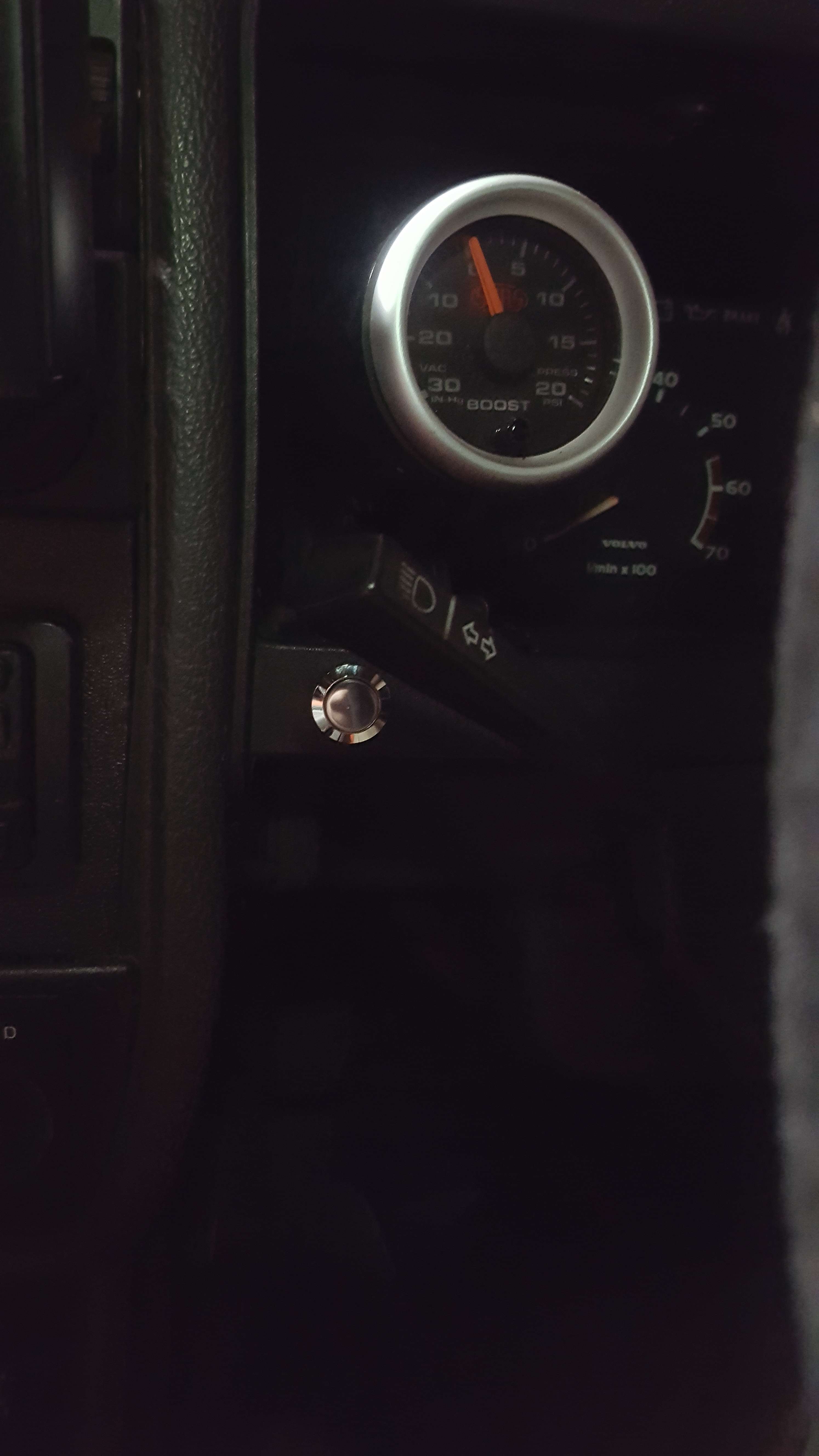
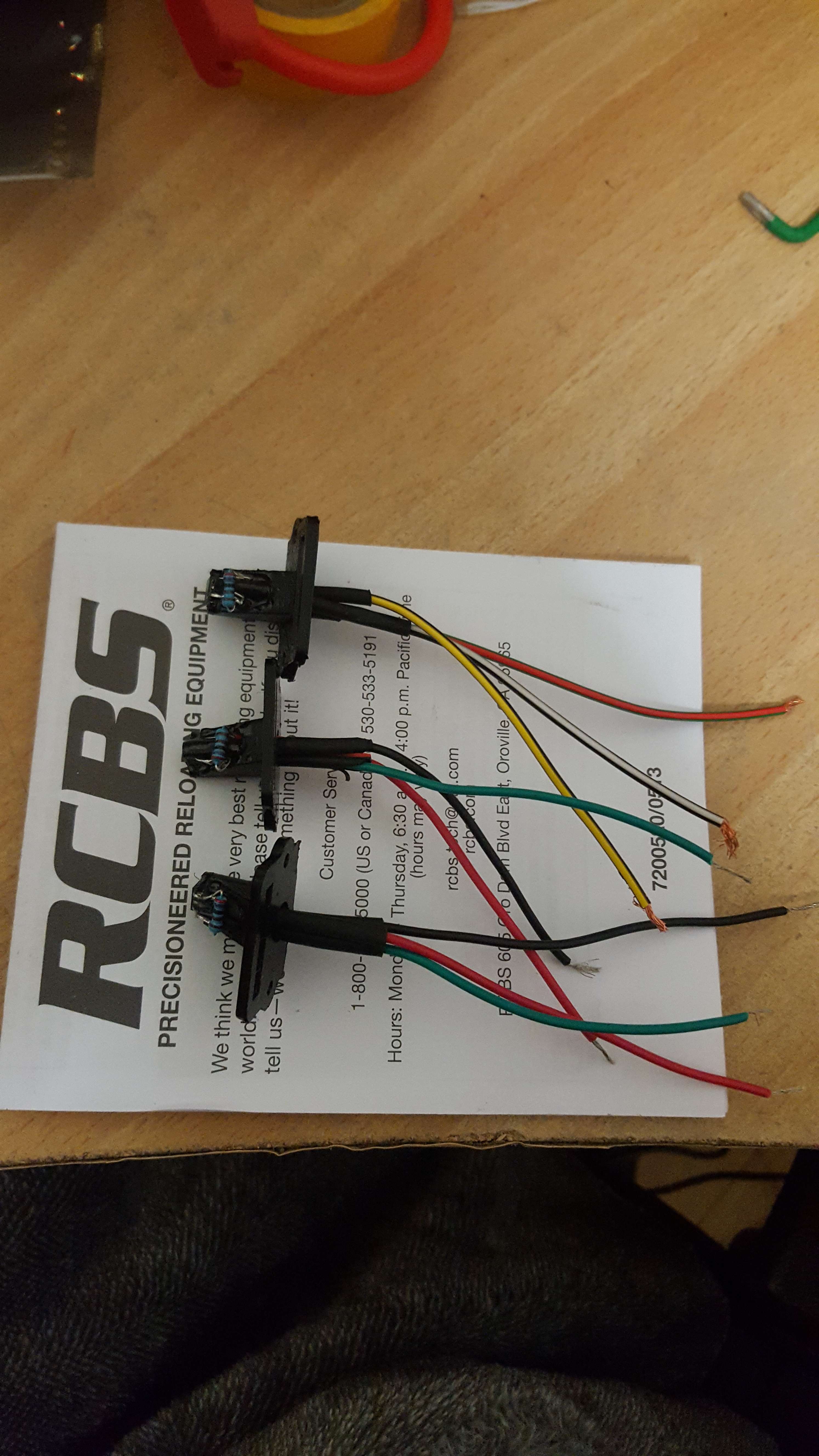
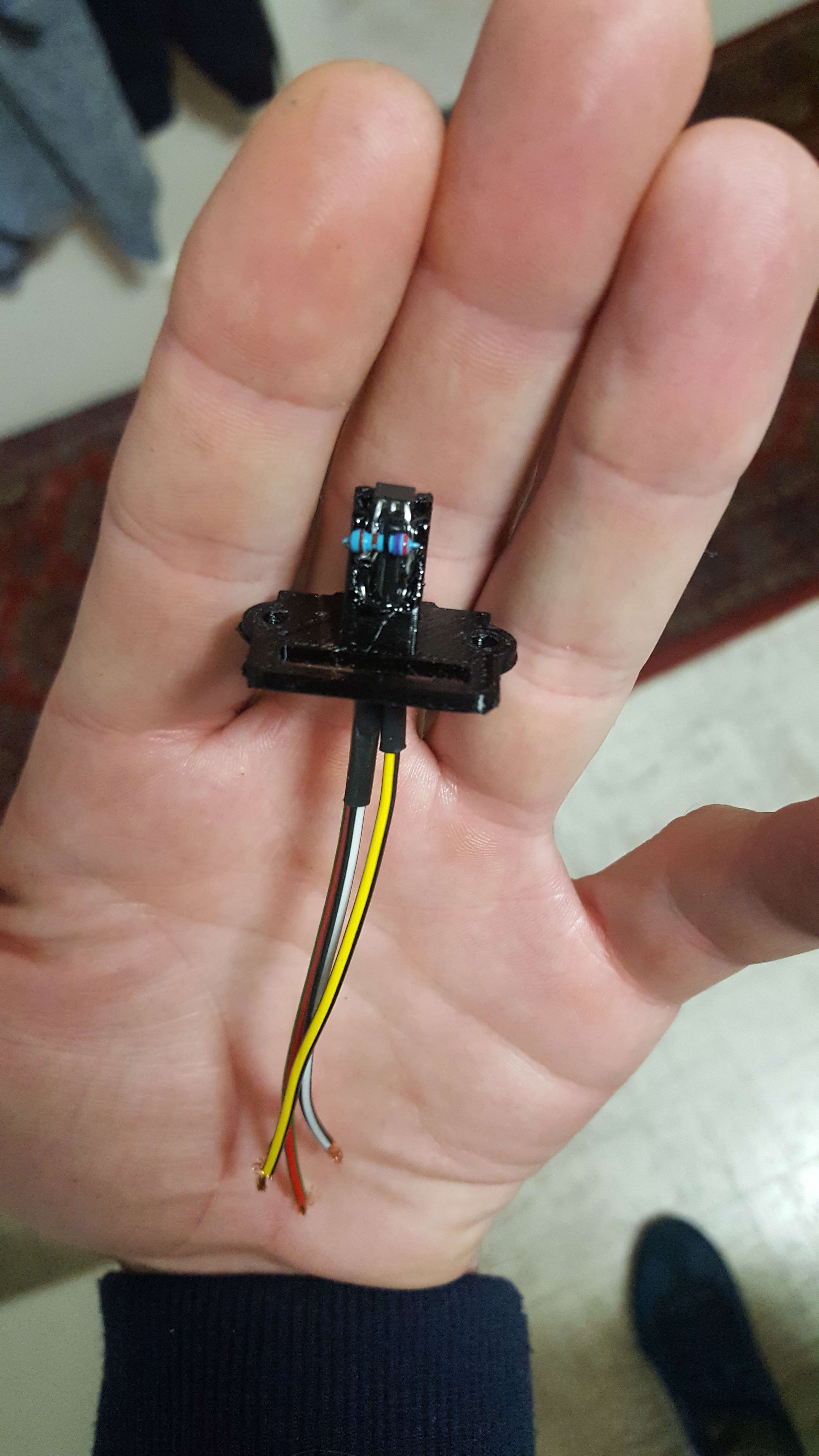
I've made my first instrument cluster speed sensor. It consists of the following:
1 x 2k7 1/4 axial resistor
2 x No.2 x 9.5mm self tapper screw
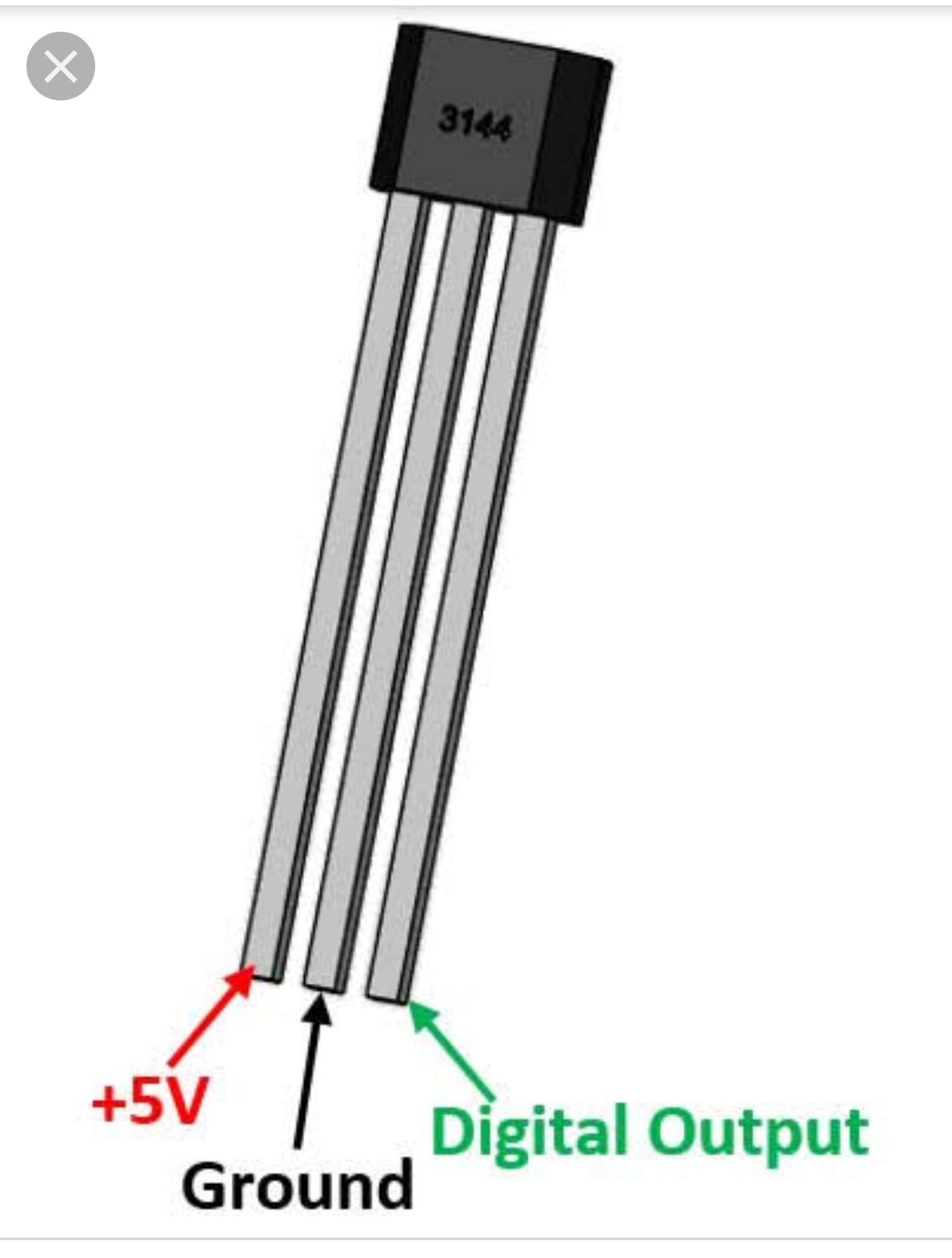
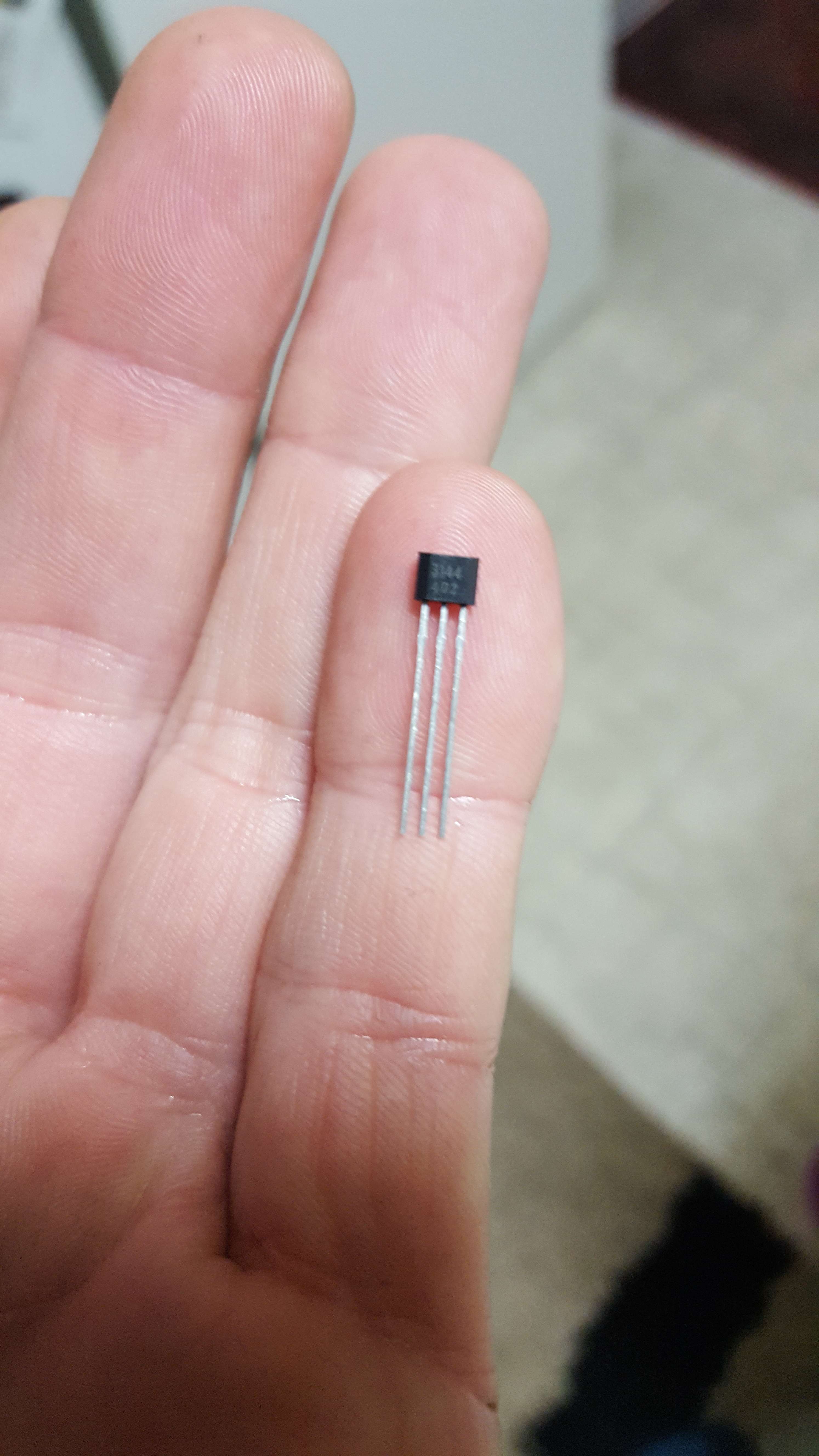
1 x A3144E through hole hall switch
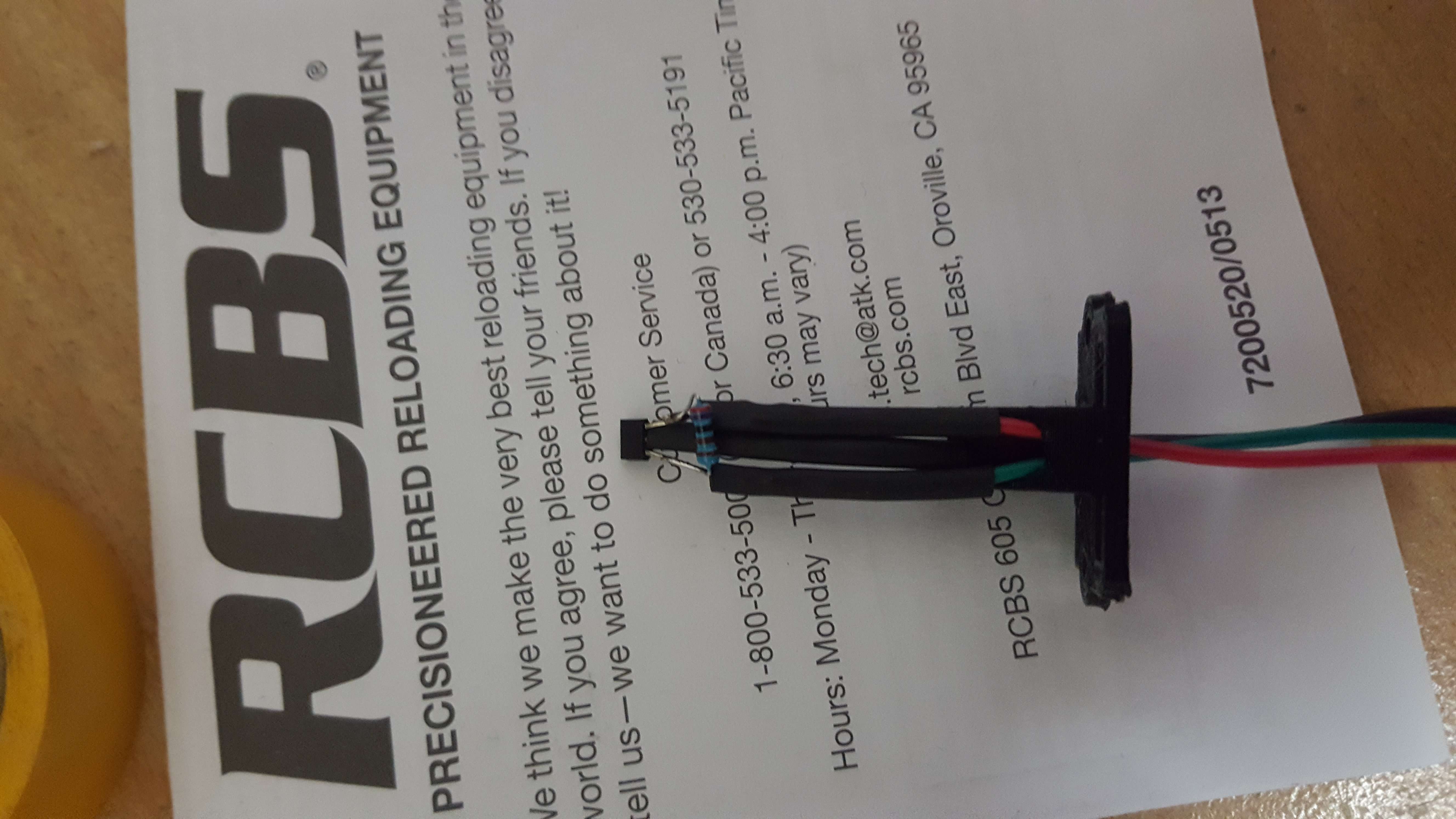
10mm x small heat shrink
3 x 7cm small gauge wire
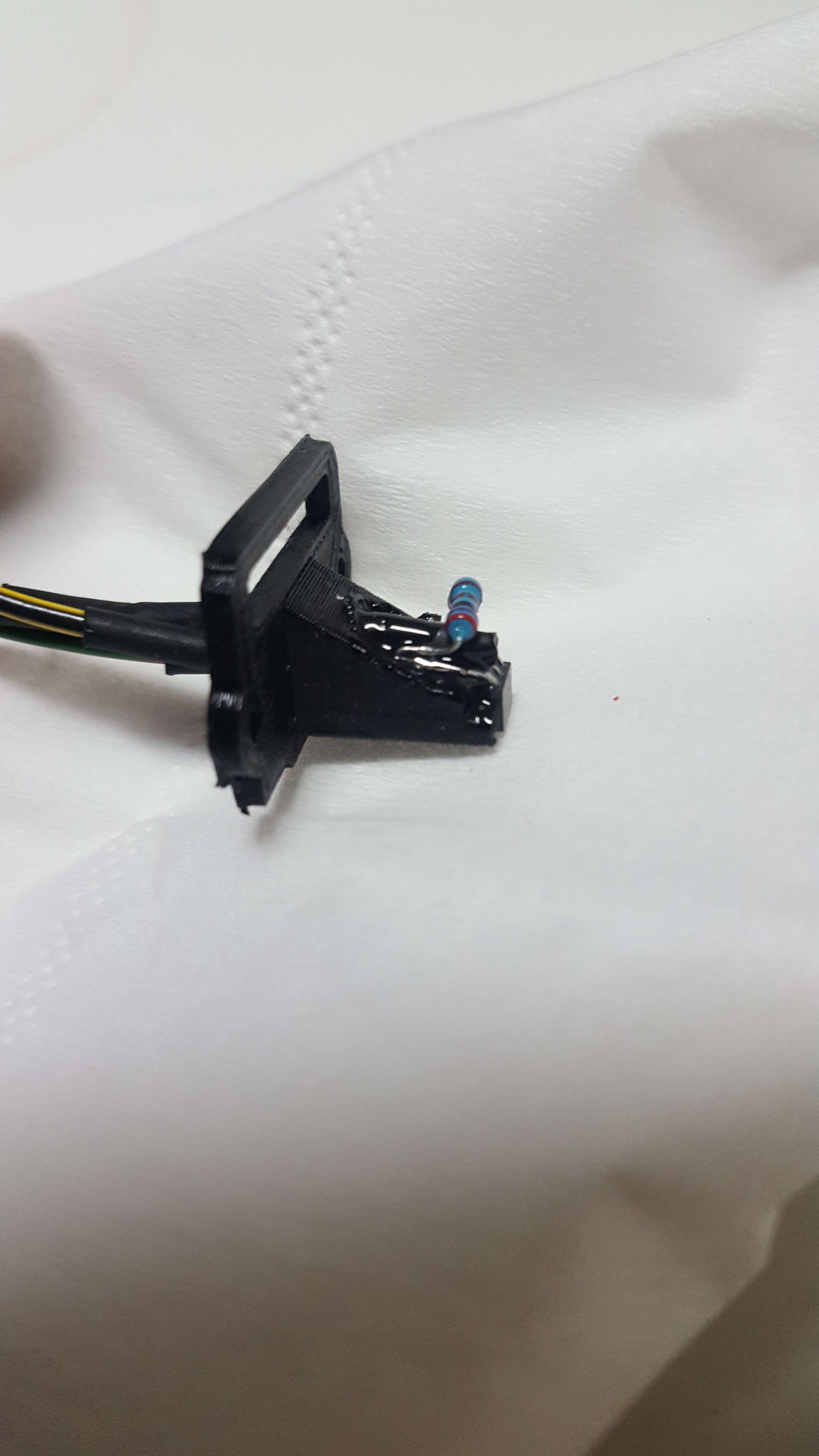
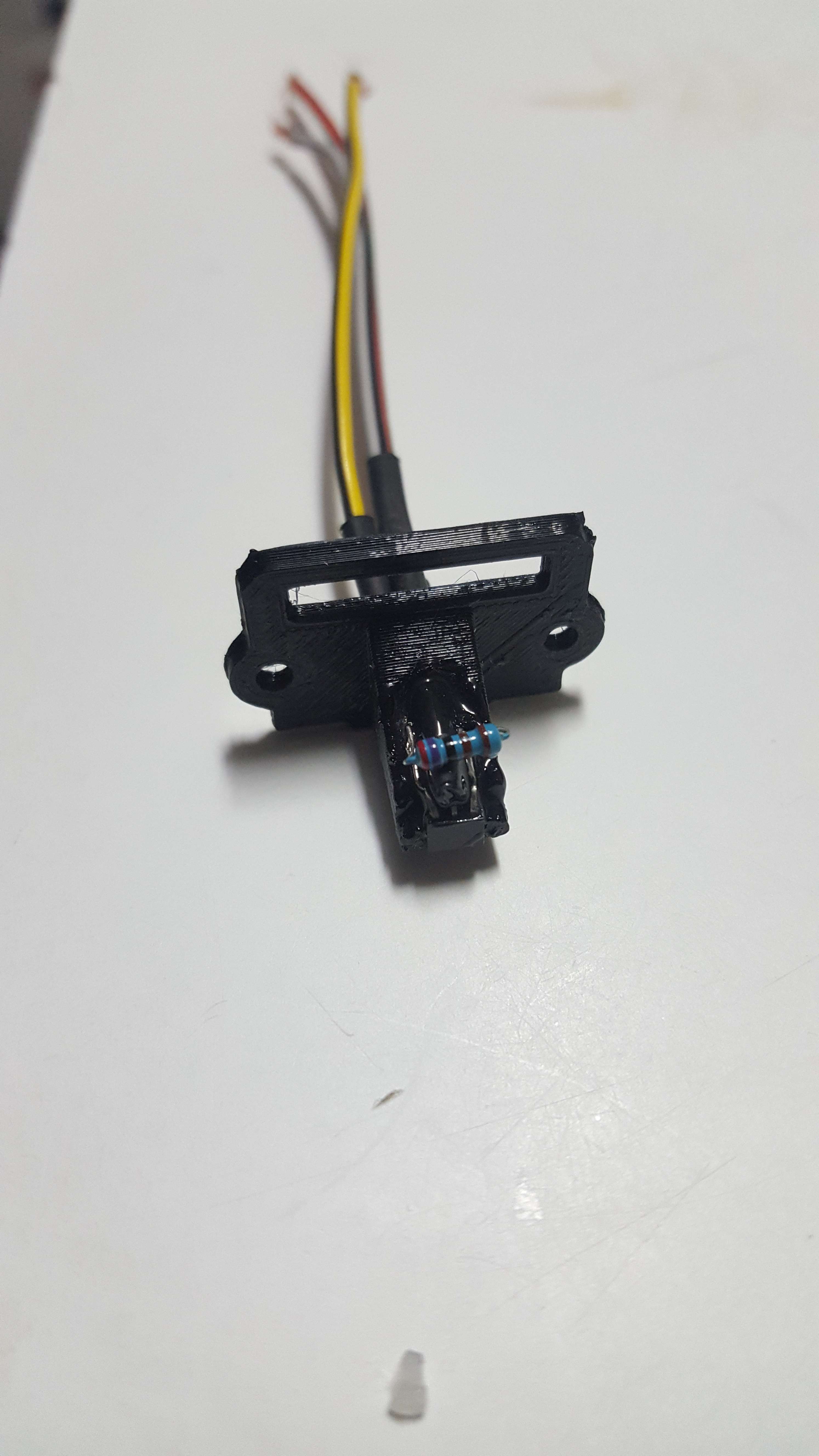
1 x 3D printed holder
Pea of epoxy glue
Link to 3d print file:
https://www.tinkercad.com/things/d7KWyZdxanN-vehicle-speedo-speed-sensor-holder-1980s-vw-volvo
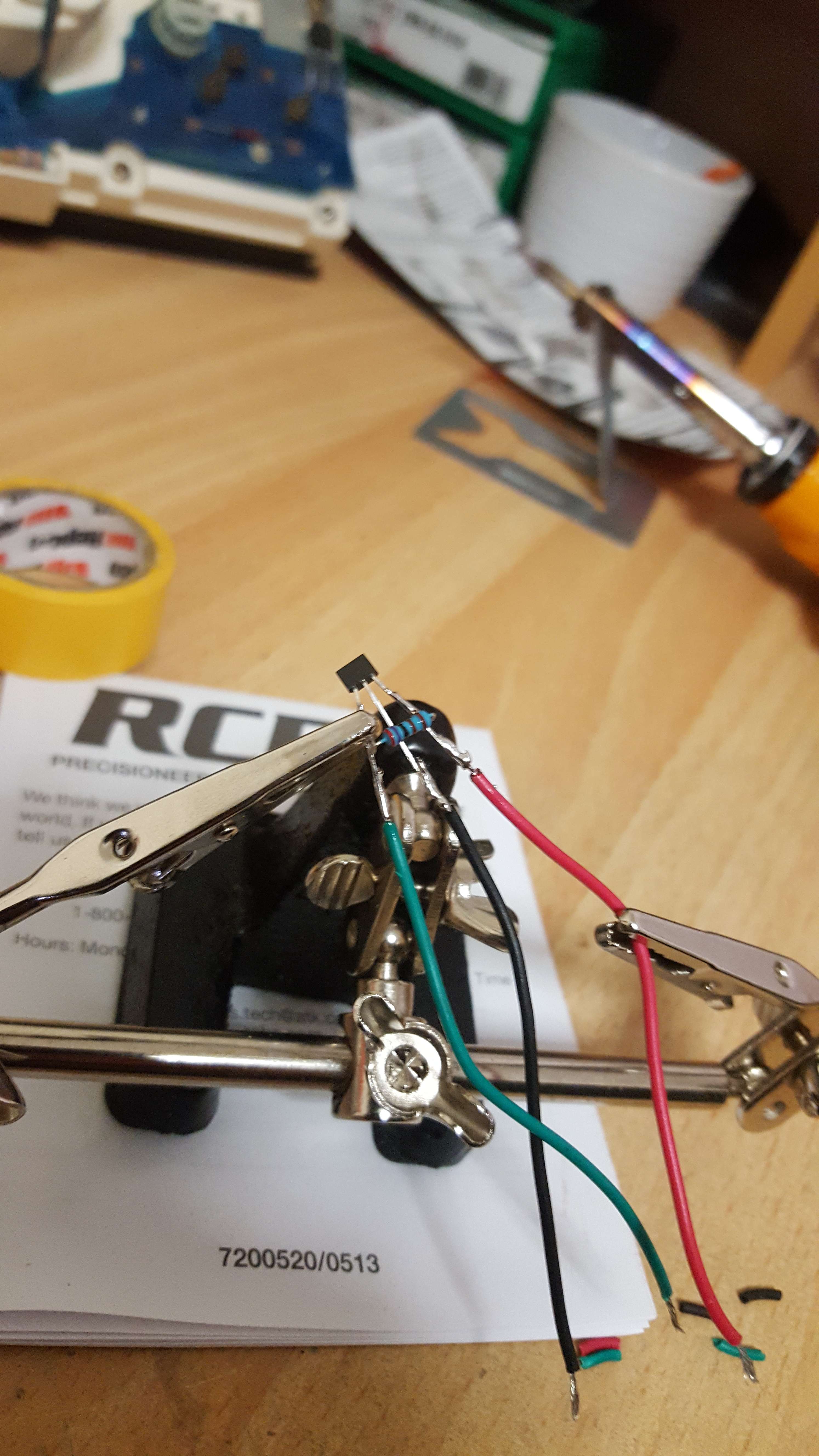
The hall sensors are so small and you need to solder the axial resistor onto the two outer prongs and wire onto all 3 prongs. I destroyed two already by overheating the hall sensor. I had to get some high flux solder (60/40 tin and lead) to do this one. I need to hook up a test light to make sure its all working before I install. I will update as I go.
Instructions from Tony at 300mania:
1. Form the hall sensor by widening out the legs a little and bending the plastic part at 45 degrees to the legs, the widest part should face out (down)
2. Form the resistor to attach to the outer 2 legs and to be bend back on itself
3. Pre-tin the resistor and sensor legs then solder, use a croc clip + tweezers jig to hold (will add photos later)
4. Strip and solder the wire to the legs, don't linger or you'll melt the resistor off
5. Put the heat shrink on the middle leg and slide up close to the hall sensor, heat to shrink (without melting the solder)
6. Fit the lot into the holder and bend the hall sensor 90 degrees, bend the resistor down flush with the holder.
7. Glue the hall sensor and wires with epoxy at both ends and the resistor, use minimal amounts to ensure the epoxy does not protrude too far. Arrange something to hold it in place while the epoxy hardens, or consider super glue initially.