Cooling fan wire diagram is for 2006 BPY engine, which is what you have. ElsaPro listed 2 wire diagrams, both look the same so I dunno why two are listed.
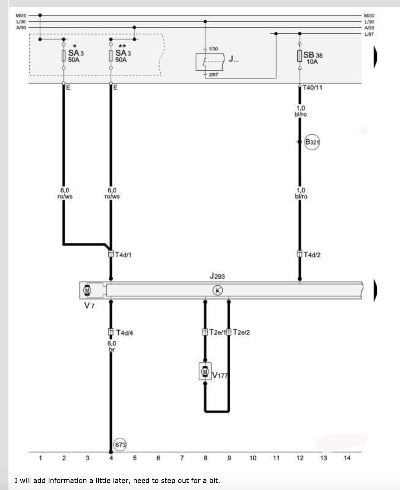
This is how the wire diagram is labeled:
Coolant Fan, Coolant Fan 2
J... - Engine Control Relay
J293 - Coolant Fan Control (FC) Control Module
SA3 - Fuse 3 (on fuse panel A)
SB38 - Fuse 38 (on fuse panel B)
T2e - Double Connector, black, on coolant fan control (FC) (front end)
T4d - 4-Pin Connector, black, on coolant fan control (FC) (front end)
T40 - 40-Pin Connector, black, on electronics box engine compartment (Connector J)
V7 - Coolant Fan
V177 - Coolant Fan 2
673 - Ground Connection 3 (on left front long member)
B321 - Plus Connection 7 (30a) (in main wiring harness)
* - ¿ Applicable Wiring Diagram for models with battery in engine compartment, engine codes AXX, BPY, BWA, BHZ, BZC
** - ¿ Applicable Wiring Diagram for models with battery in luggage compartment, engine codes BMJ, BUB
Breakdown:
SA3 is a large 50A fuse on the front side of fuse box in engine bay, third fuse from the left. Feeds the 6mm diameter red wire with white stripe (ro/ws) to fans/fan control module. As you can obviously see, it's the main power supply for the fans.
SB38 is a 10A fuse that is probably power supply for the fan control module, feeds the 1mm blue wire with red stripe (bl/ro). Upper left corner in engine bay fuse box, 3rd from left. This fuse powers: Camshaft Adjustment Valve 1 -N205-, Coolant Fan Control (FC) Control Module -J293-. If you are getting power at pin 2 of the T4d connector at fans, then this fuse and the J... relay are probably okay.
J... is labeled as engine control relay. Which engine control relay? Who the f*ck knows. I'm guessing that with the engine running, there's supposed to be a completed power circuit from it to J293. I can probably find it in the engine diagram, so if you have a problem with this circuit, let me know and I'll do some more digging.
J293 is integrated with V7 which is the main cooling fan and controls the smaller fan V177.
The black arrow just to the right of J293 is a continuation of the module onto the next page. All that is there is a wire to the module at the T4d/3 (pin #3 of 4-pin connector) connector, 0.5mm yellow with lilac stripe that is probably the control circuit from ECM connector T94/28. This circuit is likely communication so it probably won't have a regular voltage. If it operates like a LIN circuit, it will maybe be in the 10-11V range. If there was a communication error with the fan control module, there would likely be a dtc set in the ecm.