• General
  • [solved] (LH2.4 240) 1993 Engine Loom to 1991 Dash Loom

Hey all,

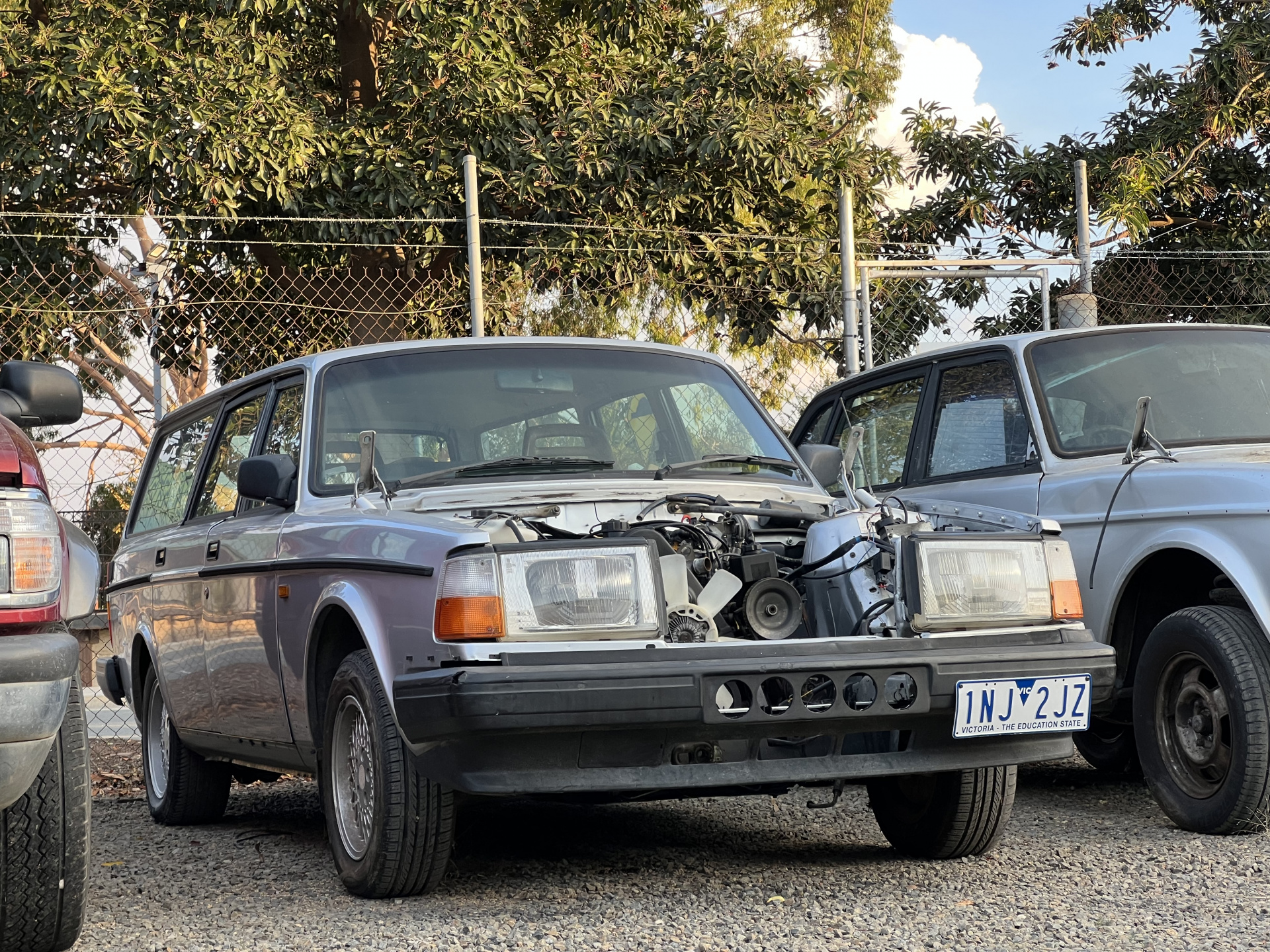
Ive just swapped a B230FX from a donor 1993 LH2.4 Sedan into my 1991 LH2.4 wagon.

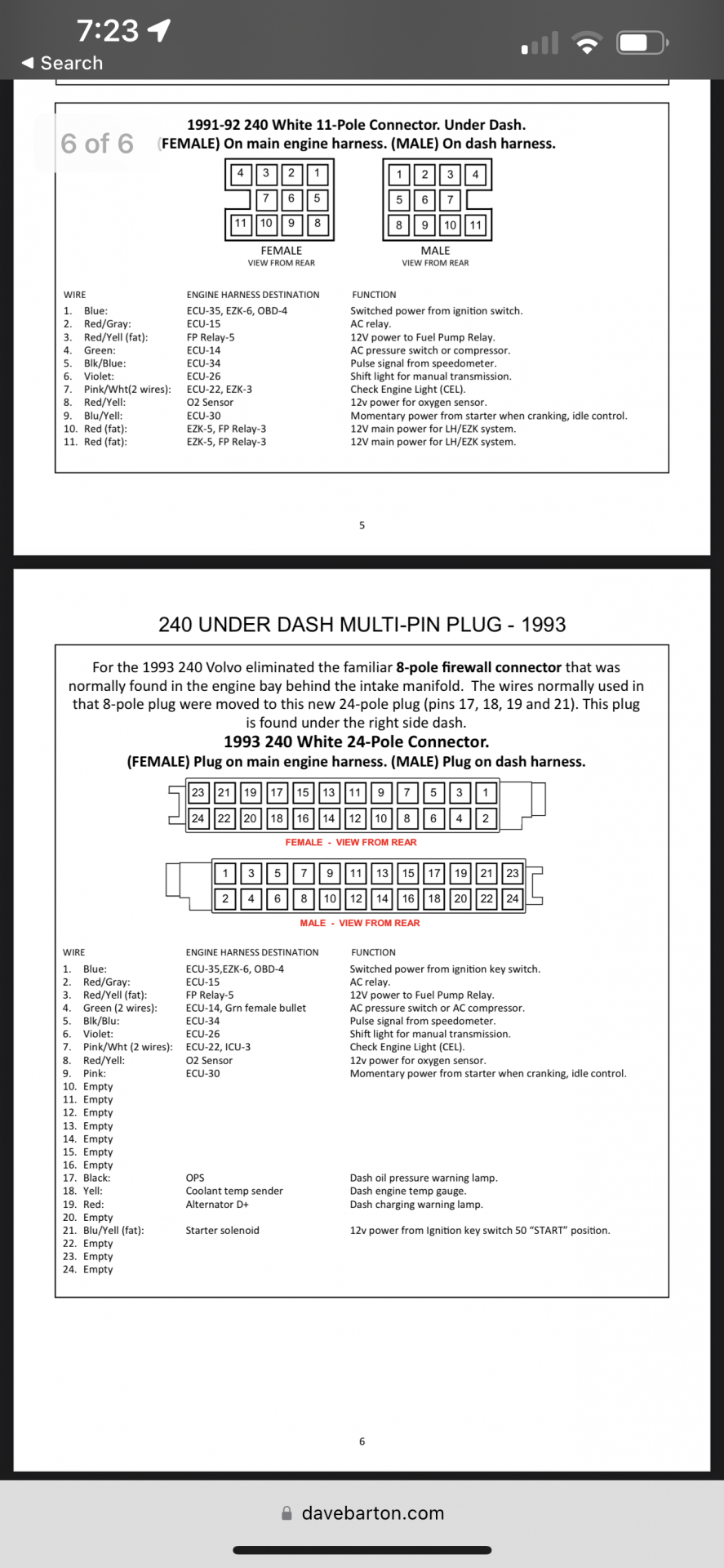
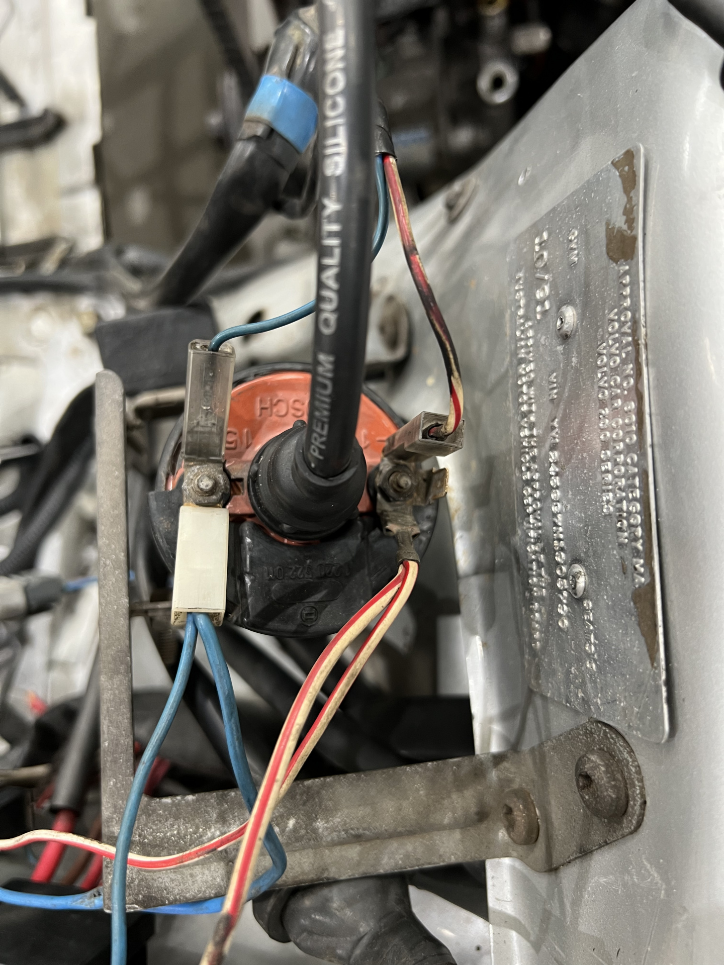
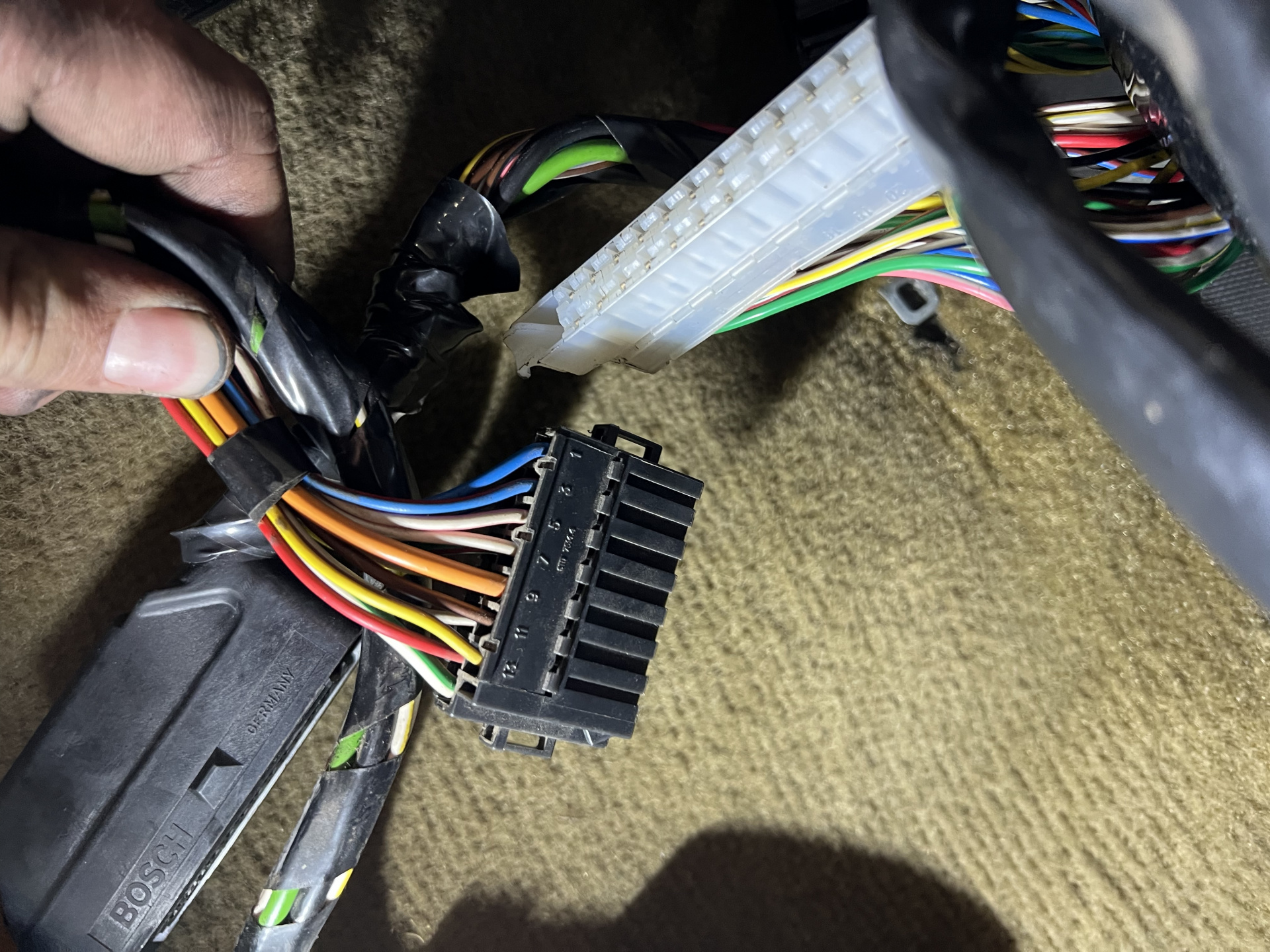
The loom on the donor engine has a large white connector after it passes through the firewall where it connects to the rest of the main harness near the EZK. My wagon has a smaller black plug.

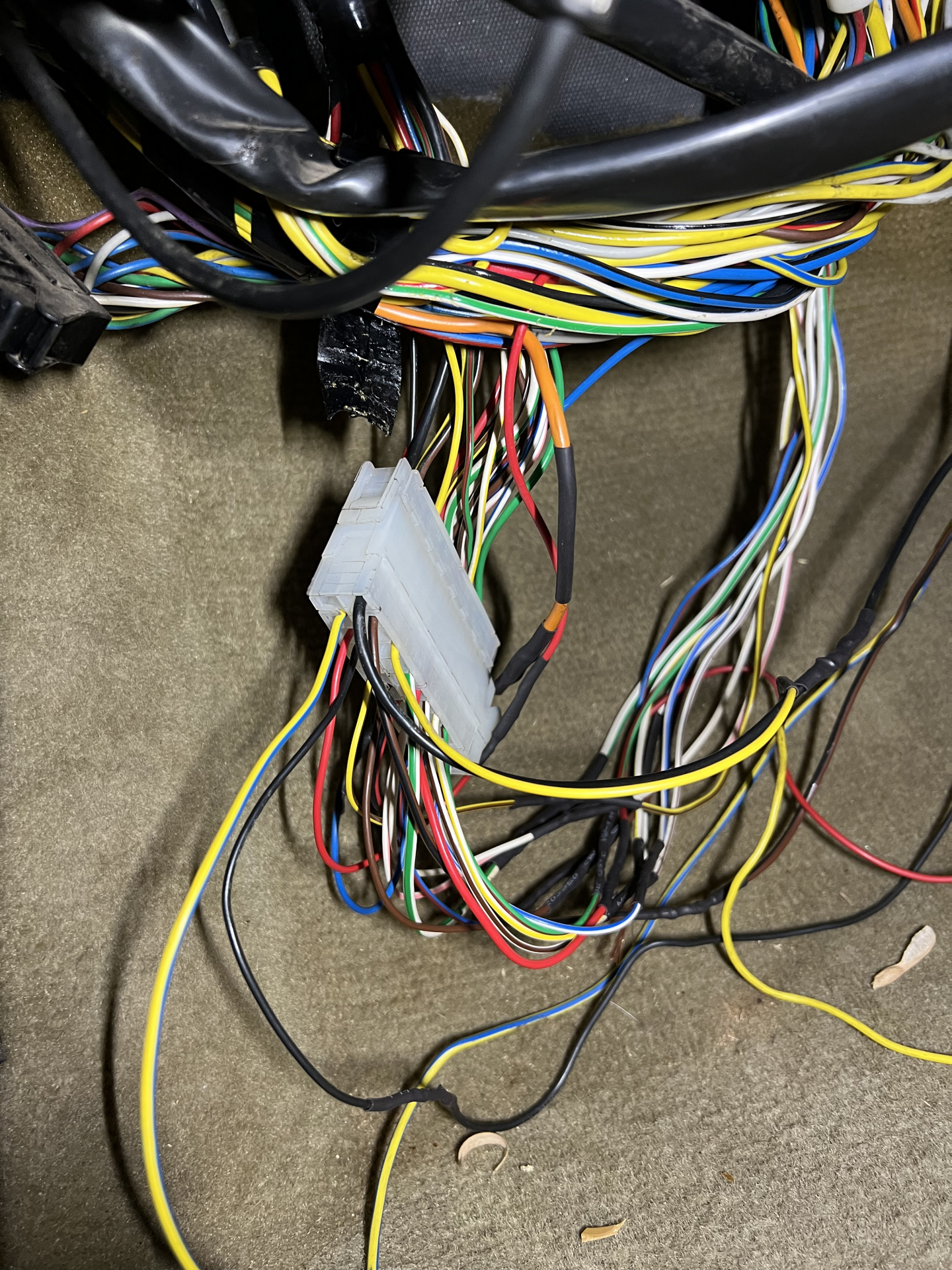
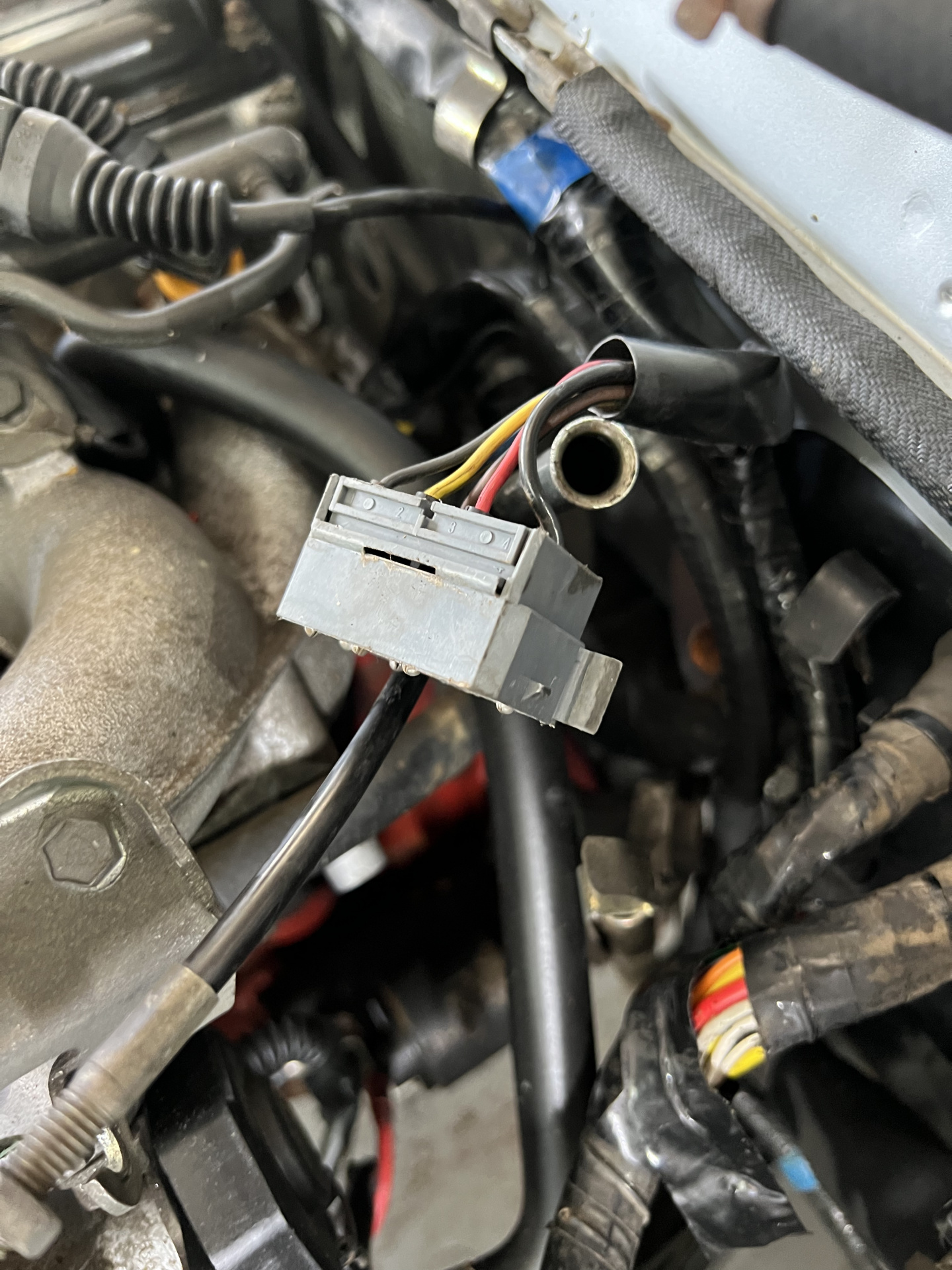
I also have a grey connection the body loom in the engine bay against the firewall which doesn’t exist on donor engine loom.

Unfortunately, I don’t have the engine loom from my original B230F that came out of the wagon.

The pictures show the grey connector near the firewall, the white connector on the late engine loom, and the black connector on the earlier loom.

Hoping I can wire in the correct plugs, but I’ll need to find a wiring diagram for both harnesses.

Cheers,

Sam

Short of finding another donor car to pull the harness from, I cannot see an easy way out of the predicament you're in

I havent worked on a 93 but I know that year got all of the final upgrades. Its possible that large white plug you see if part of these upgrades to make the harness more robust vs the dated style you see in your 91 that uses that grey plug.

That black plug is standard LH2.4 affair. When I installed LH2.4 into my 77 that originally came with Kjet I added that plug and integrated it into my harness.

This is all largely irrelevant information though. What you should do if your old harness is not damaged is to swap that onto your FX. Your FX wont care about what year LH harness is on it. Case in point is I have a B23ET that was originally motronic with an LH2.4 harness on it. As long as you plug all the sensors in the right place then youre a go. I dont think you need to go to the expense and time wasted of finding another loom. Thats crazy talk.

The problem is, all I have of the original engine loom is the EZK and black connector with about 10cm of tail from where it was cut from the rest of the loom.

I’m sure there is a way to wire the plug I need into the existing loom, but I reckon it’s going to be a mission!

You cut the original harness out of the car when you removed the original engine?

    {"embed-external":{"data":{"url":"https:\/\/cdn.ozvolvo.org\/uploads\/940MYCXELLT6\/volvo-240-1993.pdf","name":"Volvo 240 1993.pdf","type":"application\/pdf","size":480465,"displaySize":"large","float":"none","mediaID":34248,"dateInserted":"2023-04-01T02:29:43+00:00","insertUserID":71,"foreignType":"embed","foreignID":71,"embedType":"file"},"loaderData":{"type":"file","file":[],"progressEventEmitter":{"listeners":[null]}}}}

    {"embed-external":{"data":{"url":"https:\/\/cdn.ozvolvo.org\/uploads\/D9I3ABE7ZPYJ\/volvo-240-1991.pdf","name":"Volvo 240 1991.pdf","type":"application\/pdf","size":469216,"displaySize":"large","float":"none","mediaID":34249,"dateInserted":"2023-04-01T02:29:49+00:00","insertUserID":71,"foreignType":"embed","foreignID":71,"embedType":"file"},"loaderData":{"type":"file","file":[],"progressEventEmitter":{"listeners":[null]}}}}

    Looks like the main difference is the addition of the SRS airbag system in the 93. Here are the two greenbook wiring diagrams for the two systems. I think what you will need to do if you want to keep the new plug is figure out whats in it and terminate/connect wires as needed. Alternatively, it may be in your best interest to reconnect the wires you cut by using decent wire crimps and heat shrink.

    Alternatively you may be able to follow this old turbobricks article that is focused on upgrading to LH2.4 from Kjet/2.2 but it shows you what you need to make it work.

    Slowbrick

    You cut the original harness out of the car when you removed the original engine?

    Yeah, I did. I was in a rush when I was pulling the engine to fit a turbo oil drain, and instead of pulling the loom through the firewall, I cut it and rejoined it when the motor was back in. I didn’t think the connectors would fit through the hole in the firewall.

    I know now they definitely do fit. *facepalm*

    Thanks for the wiring diagrams, I’ll have a look through and see if I can work out what needs to go where.

    Thanks to Dave’s Volvo Page, I’ve found what I think is the white plug on the donor engine harness I’ve discovered.

    The ‘93 240’s had the wires from grey plug in the engine moved to a white 24 pin connector under the dash.

    Bit of an update:

    1991 has a grey 8 pin connector in the engine bay against the firewall, and a black 14 pin connector in the passenger side footwell near the EZK. Both these connectors join the engine harness to the dash harness.

    1993 has a white 24 pin connector in the passenger side footwell near the EZK.

    As I discovered on Dave’s Volvo Page, the 1993 loom eliminated the grey connector in the engine bay and re-routed those wires to the white 24 pin connector.

    I’ve compared the two wiring diagrams I linked earlier and have found only one main difference:

    1991 Injector circuit has a thick orange wire.

    1993 Injector circuit has a thick red-black wire.

    I’ll trace each colour wire back to its corresponding sensor/relay to confirm that the diagrams I’m working with are correct, but each pin number and wire colour on the black 14 pin connector matches up with the 24 pin connector.

    If that all checks out, I’lI unpin the black 14 pin connector and pull the 8 pin connector wires through the firewall in my wagon, take the dash harness side of the 24 pin connector from the donor and re-pin the wagon wires to match the late engine harness.

    Pretty specific scenario, but I figure I’ll keep updating this thread in case someone else encounters the same thing.

    Fingers crossed this works!

    The standardised ground connections are shown in the 240 factory-issued Green Books, TP-31767/1 (for 1991) and TP-32352/1 (for 1993). I have copies of both on the OTP 240 Green Book USB stick, but unfortunately can't do screenshots as LockLizard disables that function. You might get lucky by googling those TP numbers and find scanned PDFs of the Green Books.

    JFTR, there appears to be two ground connections at the inlet manifold, according to the diagrams.

      Major Ledfoot

      The standardised ground connections are shown in the 240 factory-issued Green Books, TP-31767/1 (for 1991) and TP-32352/1 (for 1993). I have copies of both on the OTP 240 Green Book USB stick, but unfortunately can't do screenshots as LockLizard disables that function. You might get lucky by googling those TP numbers and find scanned PDFs of the Green Books.

      JFTR, there appears to be two ground connections at the inlet manifold, according to the diagrams.

      Take photo of screen?

      ^ Poor resolution makes that a waste of time for an electrical diagram.

      Major Ledfoot

      The standardised ground connections are shown in the 240 factory-issued Green Books, TP-31767/1 (for 1991) and TP-32352/1 (for 1993). I have copies of both on the OTP 240 Green Book USB stick, but unfortunately can't do screenshots as LockLizard disables that function. You might get lucky by googling those TP numbers and find scanned PDFs of the Green Books.

      JFTR, there appears to be two ground connections at the inlet manifold, according to the diagrams.

      I was able to find the 1993 TP-32352/1 diagram, but found the two diagrams that @Slowbrick linked worked much better for me.

      Pulled the wires from the engine bay through the firewall and pinned everything into the new style 24 pin plug. I still need to tidy up and re-wrap the harness but waiting until I know everything is OK. I had to solder on the pins from the donor dash loom so I had male pins.

      Cranks but won’t fire, currently have no spark but power to the coil.

      That’s as far as I could get today!

      EDIT: Can’t figure out how to remove the double up image on my iPhone.

      Fixed a couple of pins that hadn’t clicked into the connector properly, also discovered I hadn’t connected the power stage somehow.. facepalm

      Despite this, I still have no spark.

      I have power to the injectors, I still need to check pulse.

      I have power to both both terminals on ignition coil, but it appears I have no ignition pulse. I checked this by placing a test light between the + and - terminals and observed while cranking.

      I’ve tested the crank angle sensor and had around 160 ohms of resistance which I think is fine.

      Not sure where to go from here to find where this start signal is lost.. any suggestions?

      Re-check all connectors

      Especially the RPM sensor (male and female pins)

      Ignition power stage, as well as all other plugs and relays

      Does your car have a radio suppression relay? If so the injectors are powered by it

        ramrod

        Re-check all connectors

        Especially the RPM sensor (male and female pins)

        Ignition power stage, as well as all other plugs and relays

        Does your car have a radio suppression relay? If so the injectors are powered by it

        The rubber shielding has broken down on the RPM sensor (crank position sensor I’m assuming), exposing the foil shielding. Not sure if that would be causing any issues.. I think I might replace it anyway instead of trying to fix it.

        AFAIK none of the 240s had a radio suppression relay.

        Next time I’ll re-check all connectors again as it’s possible I’ve missed more.

        Something I did find though, I have a total of 3 blue and 3 red-white wires at the coil. Schematics show 1 blue to the power stage, 1 to ignition switch, 1 red-white to power stage and 1 to tacho. The remaining blue and red-white wires have been cut, and I can’t find where they go.

        I believe the coil and starter motor need to be connected together